
Gas detection device with a detector and with a compensator and gas detection process with such a gas detection device

a gas detection device and detector technology, applied in the direction of measurement devices, instruments, material heat development, etc., can solve the problems of not being able to achieve significant not being able to oxidize a sufficient quantity of a combustible target gas, and other differences between the detector and the compensator

Pending Publication Date: 2022-08-25
DRAGER SAFETY
View PDF0 Cites 2 Cited by
  • Summary
  • Abstract
  • Description
  • Claims
  • Application Information

AI Technical Summary

Benefits of technology

The patent describes a system that uses two control circuits to electrically insulate a wire and prevent short-circuits. The two circuits can have different settings or time courses, allowing them to be adapted to different requirements and manufacturing processes. The system also compensates for any differences in the electrical properties of the circuit components, ensuring accurate detection and control even during changes in the environment. The technical effects of this system include improved safety, flexibility, and better accuracy in gas detection and control.

Problems solved by technology

Therefore, only the detector is capable of oxidizing the target gas to a significant extent, but not the compensator.
By contrast, other differences between the detector and the compensator are not capable of bringing about this significant difference.
If the detector has a too small oxidating surface or too little catalytic material, then it may happen that after some time the detector is no longer capable of oxidizing a sufficient quantity of a combustible target gas and hence is no longer capable of detecting this target gas.
In particular, it is often not possible to provide such a detector with a sufficiently large oxidating surface and quantity of the catalytic material.
The reliability may not suffice.
In addition, some target gases or other gases, which may be present in the area to be monitored, may damage the catalytic material of a detector, provided the detector extends in a plane.
However, a gas detection device with such a filter cannot also detect a target gas which cannot pass the filter and can therefore not reach the interior of the housing.
The energy consumption, but also the reliability, is lower in the monitoring mode.
In the measuring mode, the reliability but also the energy consumption are higher.
However, this indicator is in relatively many cases a false alarm, i.e., no target gas is present in reality.
The configuration with the different voltages, which are applied to the detector, leads to an especially low energy consumption.
However, the energy consumption is then higher.

Method used


Image

  • Gas detection device with a detector and with a compensator and gas detection process with such a gas detection device
  • Gas detection device with a detector and with a compensator and gas detection process with such a gas detection device
  • Gas detection device with a detector and with a compensator and gas detection process with such a gas detection device

Examples


Embodiment Construction

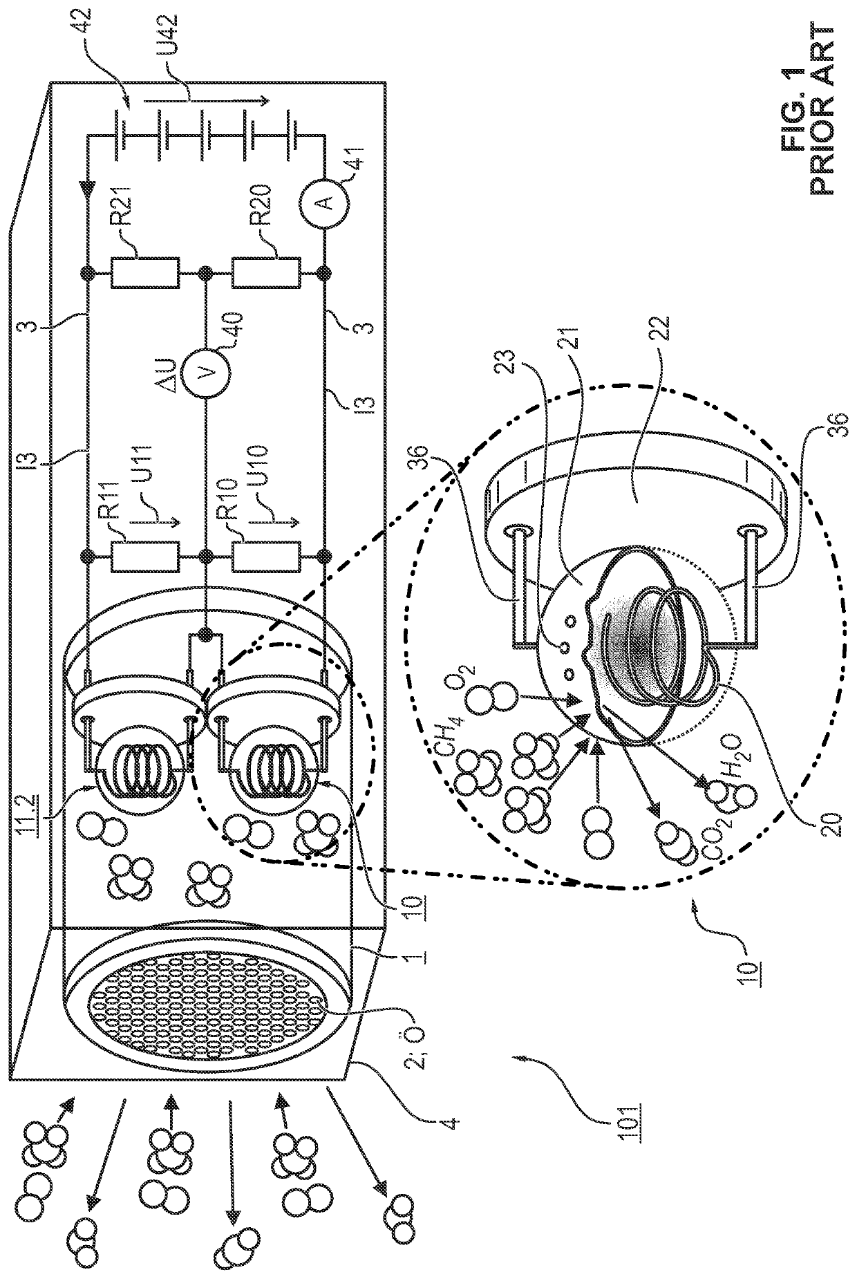
[0124]Referring to the drawings, the gas detection device according to the exemplary embodiment monitors a spatial area for at least one predefined combustible target gas and uses a principle known from the state of the art to detect the target gas. The gas detection device comprises a detector and a compensator, which are both arranged in the interior of a housing of the gas detection device. A gas mixture from an area to be monitored, which may contain the target gas, flows into the interior of the housing and reaches both the detector and the compensator. The gas detection device may be provided with a pump that suctions in the gas mixture. The gas detection device may be configured such that the gas mixture by itself diffuses into the interior of the housing.

[0125]The detector is capable of oxidizing a combustible target gas. During the oxidation, the target gas reacts chemically with oxygen under the effect of the detector, and water and carbon dioxide are formed. During this c...


PUM


Abstract

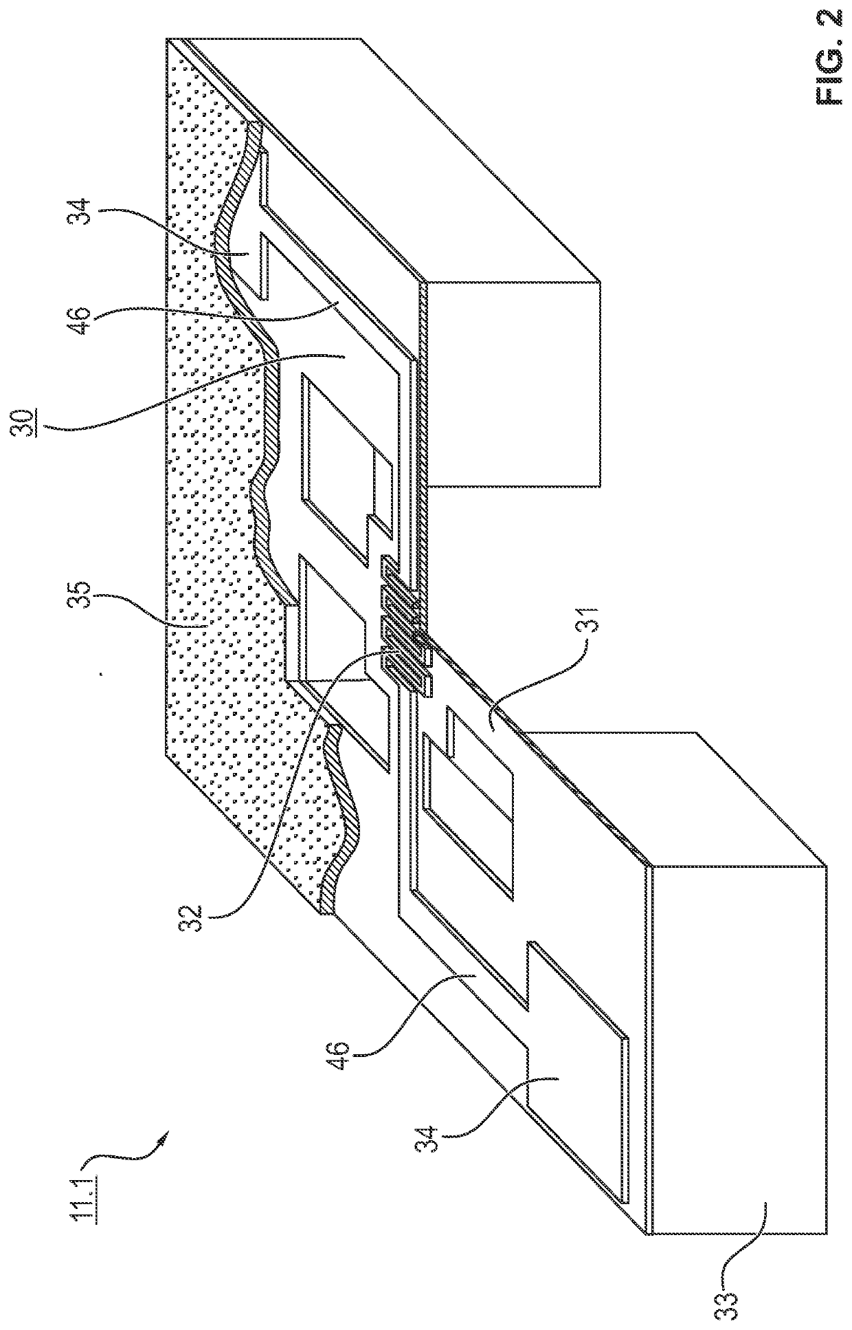
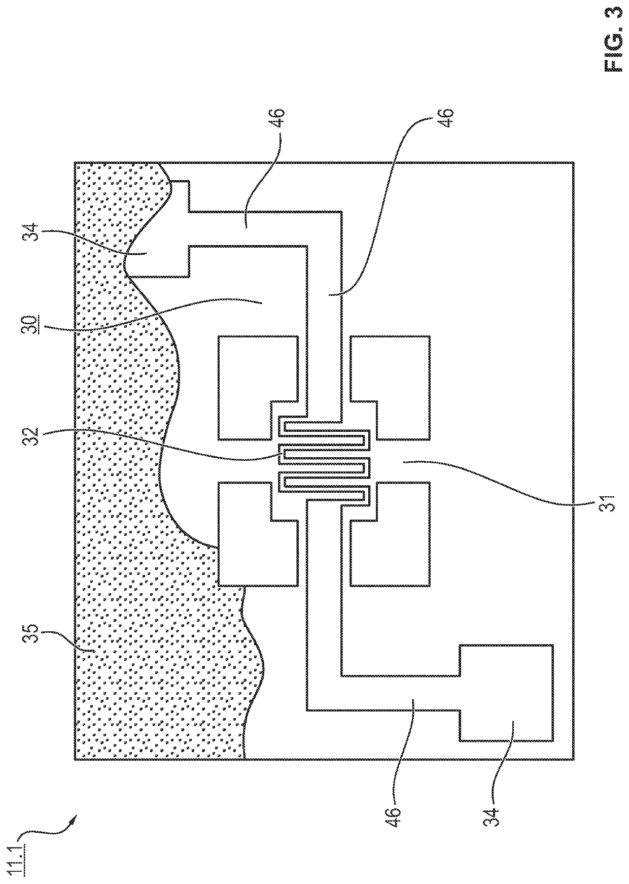
A gas detection device and a gas detection process monitor an area for a combustible target gas. A detector (10), a compensator (11.1), a sensor array (40, 41) and an analysis unit (9) are arranged in a gas detection device housing. The detector includes an electrically conductive wire with a heating segment (20), electrical insulation around the wire and a catalytic material in the electrical insulation. The compensator extends in a plane and includes an electrical strip conductor (32) with a heating segment and a carrier plate for the strip conductor. The gas detection device applies an electrical voltage to the detector and to the compensator. The detector oxidizes the target gas with the heating segment. The sensor array measures detection variables (U10, U11) for the detector and the compensator. The analysis unit compares the two detection variables to determine if a combustible target gas is present.

Description

CROSS REFERENCE TO RELATED APPLICATIONS[0001]This application claims the benefit of priority under 35 U.S.C. § 119 of German Application 10 2021 104 074.4, filed Feb. 22, 2021, the entire contents of which are incorporated herein by reference.TECHNICAL FIELD[0002]The present invention pertains to a gas detection device and to a gas detection process, which are capable of monitoring an area for at least one defined gas, below: for a target gas to be detected, wherein the target gas or a target gas is combustible in a temperature range, which may occur in the area to be monitored, and is oxidized by the gas detection device and, as a result, is detected. The area to be monitored is, for example, a mine, a refinery, a warehouse, or a heating system operated with combustible gas or even a transport vehicle.TECHNICAL BACKGROUND[0003]Gas detection devices, which comprise a detector and a compensator, have become known. Both the detector and the compensator are heated by an electrical volt...

Claims


Application Information

Patent Timeline
IPC IPC(8): G01N27/16G01N7/08
CPCG01N27/16G01N7/08G08B21/16G01N25/30G01N33/0063G08B29/24G01N33/0047
Inventor OSSWALD, JÜRGENPÖTHIG, TOMRUGE, JAN PHILIPP
Owner DRAGER SAFETY
Learn More