Refrigeration system

a technology of refrigerating system and evaporator, which is applied in the direction of cooling fluid circulation, domestic cooling apparatus, lighting and heating apparatus, etc., can solve the problems of significant reduction of heat exchanger efficiency, two-phase maldistribution problem, and efficiency reduction, so as to improve the evaporator capacity, reduce vapor quality, and substantially enhance the evaporator capacity

Active Publication Date: 2006-01-26
CARRIER CORP
View PDF5 Cites 27 Cited by
  • Summary
  • Abstract
  • Description
  • Claims
  • Application Information

AI Technical Summary

Benefits of technology

[0009] In the current invention the superheating heat exchanger is sized for complete evaporation of the non- evaporated liquid portion and provides a superheat at its low-pressure side outlet as required at evaporators outlets in each particular application. Since a superheating zone is removed from the evaporator, the evaporator capacity is substantially enhanced. Also, the reduced vapor quality at the evaporator inlet leads to improvement of the evaporator capacity. Since in the current invention the superheating heat exchanger involves just a portion of the entire mass flux provided by the compressor, costs and dimensions of the superheating heat exchanger are reduced as well.

Problems solved by technology

The non-uniform distribution of two phase refrigerant in parallel tubes, for example in mini- or micro-channel heat exchangers, can significantly reduce heat exchanger efficiency.
This is called maldistribution and is a common problem in heat exchangers with parallel refrigerant paths.
Two-phase maldistribution problems are caused by the difference in density of the vapor and liquid phases.
In addition to the reduction of efficiency, two phase maldistribution may result in damage to the compressor because of liquid slugging through the evaporator.

Method used


Image

  • Refrigeration system
  • Refrigeration system
  • Refrigeration system

Examples


Embodiment Construction

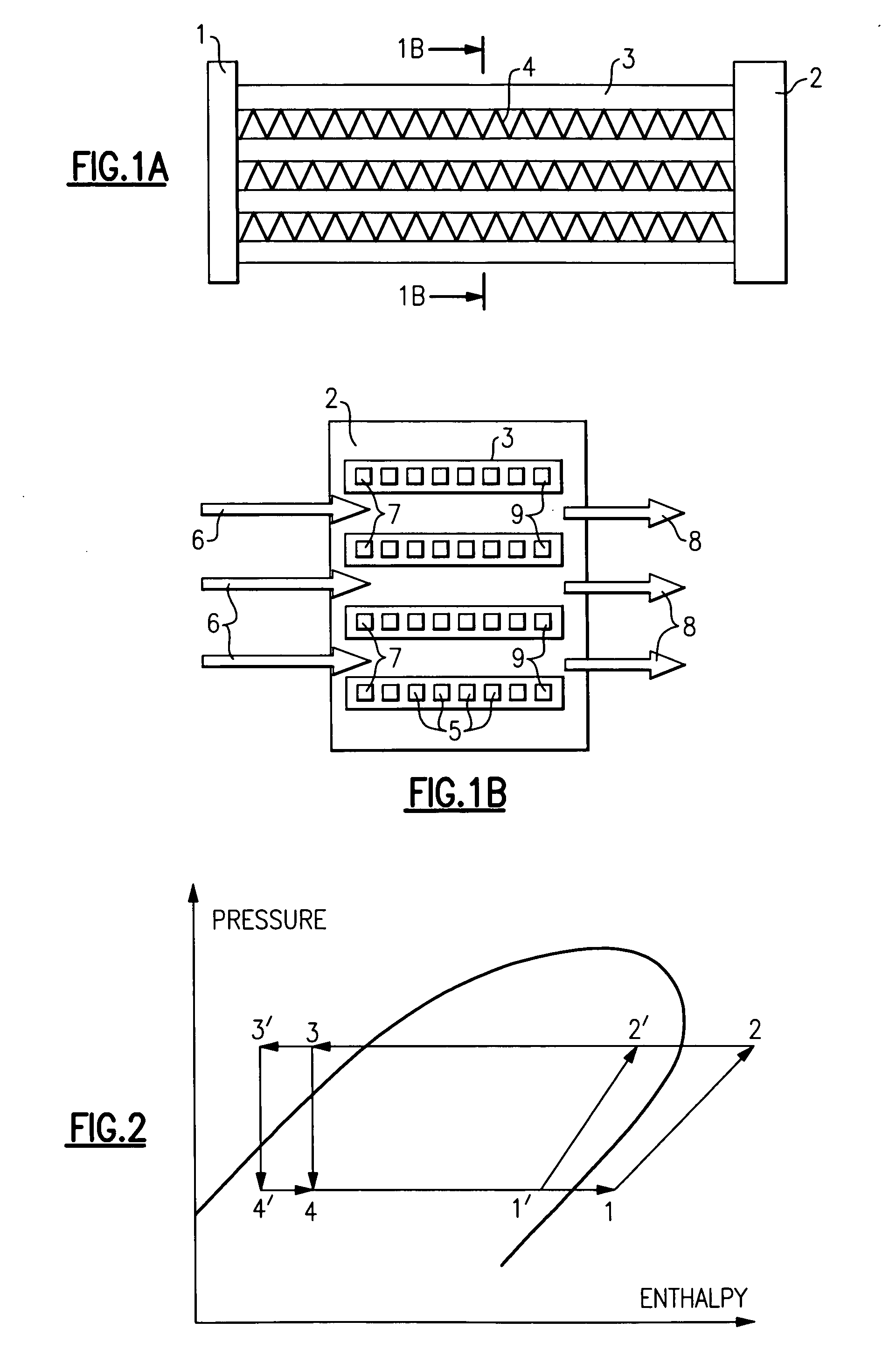
[0022]FIG. 1 shows a mini-channel or micro-channel heat exchanger with inlet header 1, outlet header 2, and tubes 3 interlaced with fins 4 externally exposed to a fluid to be chilled or cooled in the heat exchanger. As shown on the cross-sectional view, each tube 3 consists of a number of channels 5 to carry evaporating refrigerant. In the inlet to the inlet header 1 two-phase refrigerant is delivered to each tube and to each channel of tubes. Fluid inlet 6 faces first channels 7 of each tube and fluid outlet 8 faces last channels 9 of each tube. Obviously, this arrangement is a cross flow one.

[0023] The first challenge is to distribute equal amount of liquid and vapor portions of two-phase refrigerant between each tube. The second challenge is to distribute equal liquid and vapor portions of two-phase refrigerant between each channel of each tube. Refrigerant distributors have been useful to resolve the first challenge, but, the second challenge has remained unsolved. For example,...


PUM


Abstract

In a refrigeration system having a pressurizer, a condenser, an expansion device and an evaporator, with the evaporator having an inlet header, an outlet header, and a plurality of channels therebetween, the outlet header has a liquid outlet and a vapor outlet and provision is made for separation of refrigerant liquid from refrigerant vapor. The liquid refrigerant is passed through a superheating heat exchanger to obtain complete evaporation and superheating prior to passing to the pressurizer. Various other features are provided to enhance the system operation.

Description

CROSS REFERENCE TO RELATED APPLICATION [0001] This application claims priority to and the benefit of U.S. Provisioanl Patent Application Ser. No. 60 / 587,793, filed Jul. 14, 2004, and entitled REFRIGERATION SYSTEM, which application is incorporated herein by this reference.TECHNICAL FIELD [0002] The invention relates generally to refrigeration systems and, more particularly to evaporators with parallel tubes requiring distribution of two-phase refrigerant. [0003] The non-uniform distribution of two phase refrigerant in parallel tubes, for example in mini- or micro-channel heat exchangers, can significantly reduce heat exchanger efficiency. This is called maldistribution and is a common problem in heat exchangers with parallel refrigerant paths. Two-phase maldistribution problems are caused by the difference in density of the vapor and liquid phases. [0004] In addition to the reduction of efficiency, two phase maldistribution may result in damage to the compressor because of liquid sl...

Claims


Application Information

Patent Timeline
Patent Type & Authority Applications(United States)
IPC IPC(8): F25B41/00F25B39/02
CPCF25B13/00F25B40/00F25B41/00F25B2341/0011F25B2700/21175F25B2400/05F25B2400/052F25B2400/23F25B2600/2513F25B2341/0661F25B41/385F25B39/02
Inventor GORBOUNOV, MIKHAIL B.SANGIOVANNI, JOSEPH J.VAISMAN, IGOR B.
Owner CARRIER CORP
Why Eureka
Try Eureka