Expandable percutaneous sheath

Inactive Publication Date: 2006-02-16
WARSAW ORTHOPEDIC INC
View PDF53 Cites 26 Cited by
  • Summary
  • Abstract
  • Description
  • Claims
  • Application Information

AI Technical Summary

Benefits of technology

[0013] In one embodiment where the percutaneous access sheath is used to facilitate the insertion of an orthopedic spinal stabilization implant that is formed in situ, a percutaneous access sheath may advantageously be first inserted

Problems solved by technology

Additionally, the vertebrae and associated connective elements are subject to injuries, including fractures and torn ligaments and surgical manipulations, including laminectomies.
T

Method used


Image

  • Expandable percutaneous sheath
  • Expandable percutaneous sheath
  • Expandable percutaneous sheath

Examples


Example

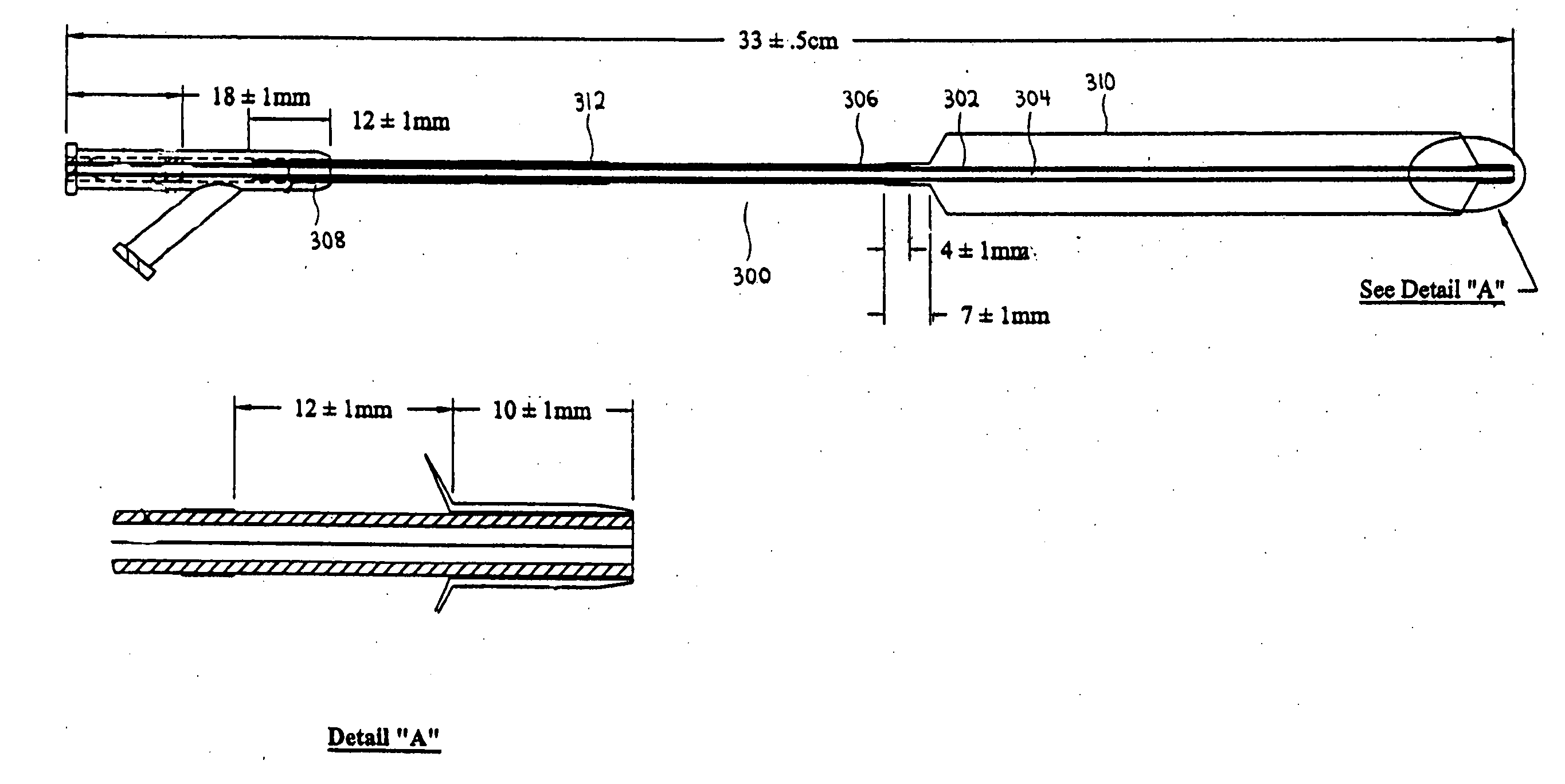
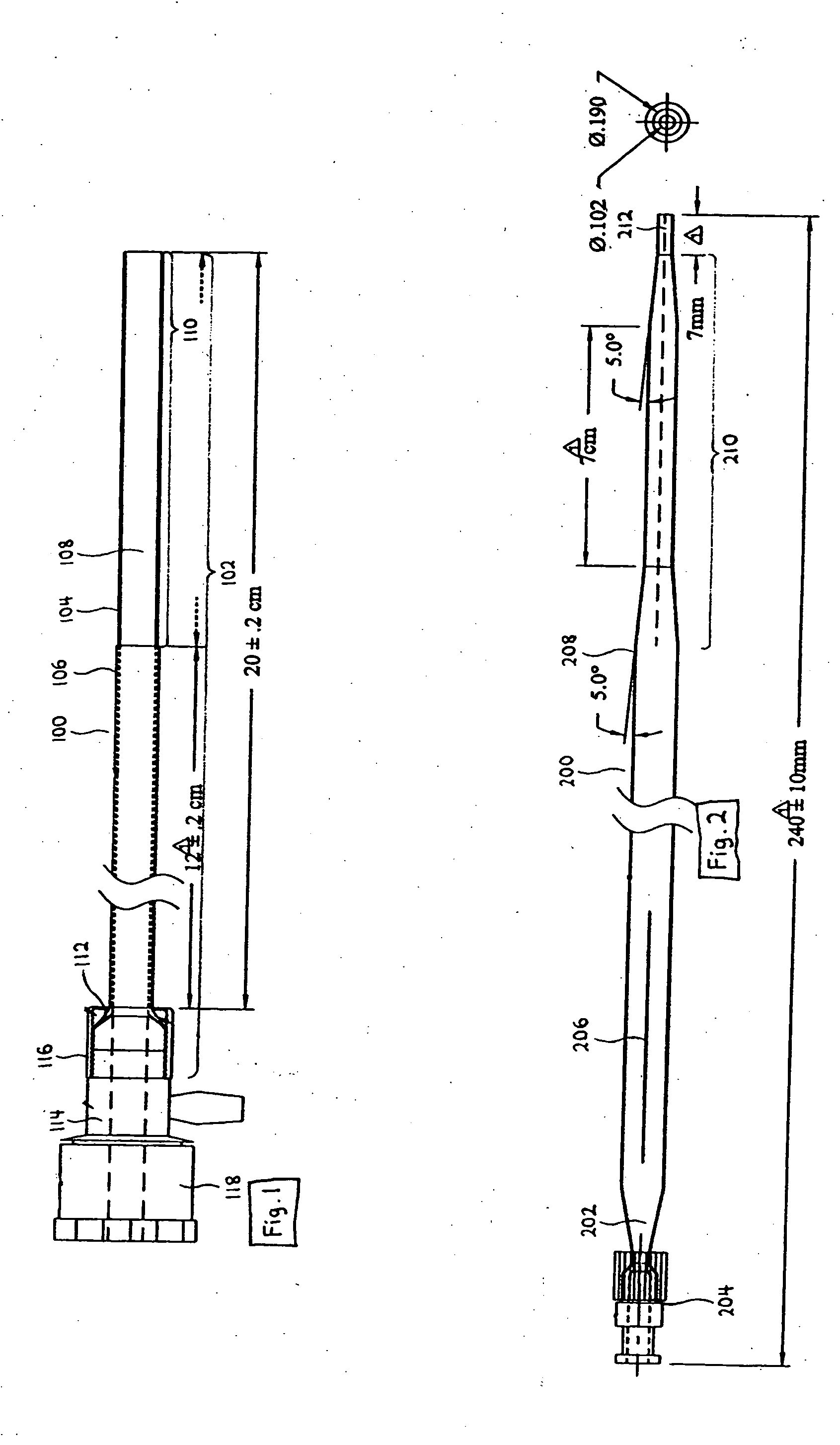
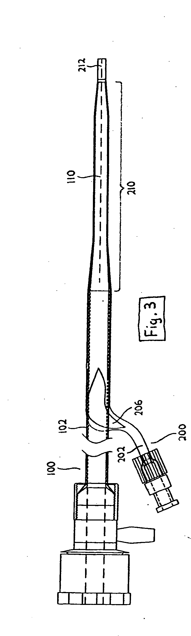
[0027]FIG. 1 is an overview of the percutaneous access sheath 100. It generally comprises an elongate tubular body with an axial lumen, and is designed to provide percutaneous access to a diagnostic or treatment site in the body. The elongate tubular body has a proximal section and a distal section 110. The length of these two sections can be varied according to clinical need, as will be understood by those skilled in the art with reference to this disclosure. The distal section 110 is expandable from a first, smaller cross-sectional profile to a second, larger cross-sectional profile. The first, smaller cross profile of the distal section 110 eases its insertion into the percutaneous treatment site. After insertion, the distal section 110 is expanded to a second, larger cross-sectional profile to provide a larger passageway for surgical instruments to reach the percutaneous treatment site.

[0028] In the illustrated embodiment, the percutaneous access sheath 100 is made of a double-...


PUM


Abstract

Disclosed is an expandable percutaneous sheath, for introduction into the body while in a first, low cross-sectional area configuration, and subsequent expansion to a second, enlarged cross-sectional configuration. The sheath is maintained in the first, low cross sectional configuration by a removable tubular restraint. In one application, the sheath is utilized to introduce a formed in place orthopedic fixation rod such as for use in spinal fixation procedures.

Description

[0001] This is a continuation of U.S. application Ser. No. 10 / 188,732, filed Jul. 2, 2002, which is hereby incorporated by reference in its entirety.BACKGROUND OF THE INVENTION [0002] 1. Field of the Invention [0003] The present invention relates to medical devices and, more particularly, to methods and devices for forming a percutaneous channel. In one application, the present invention relates to a minimally invasive procedure to insert an orthopedic fixation or stabilization implant into the body, such as a formed in situ spinal stabilization rod. [0004] 2. Description of the Related Art [0005] The vertebrae and associated connective elements are subject to a variety of diseases and conditions which cause pain and disability. Among these diseases and conditions are spondylosis, spondylolisthesis, vertebral instability, spinal stenosis and degenerated, herniated, or degenerated and herniated intervertebral discs. Additionally, the vertebrae and associated connective elements are s...

Claims


Application Information

Patent Timeline
IPC IPC(8): A61M29/00A61B17/00A61B17/56A61B17/34A61B17/88A61M25/00A61M25/06
CPCA61B17/3431A61B17/3439A61B17/7001A61B17/7083A61M2025/0024A61B2017/00336A61B2017/00557A61M25/06A61M25/0662A61B17/8872A61B17/88
Inventor NGUYEN, THANH VANTEITELBAUM, GEORGE P.PHAM, TO V.SHAOLIAN, SAMUEL M.
Owner WARSAW ORTHOPEDIC INC
Why Eureka
Try Eureka