Kinetic anchoring deployment system

US20070219565A1Inactive Publication Date: 2007-09-20SAADAT VAHID

Image

  • Kinetic anchoring deployment system
  • Kinetic anchoring deployment system
  • Kinetic anchoring deployment system

Examples


Embodiment Construction

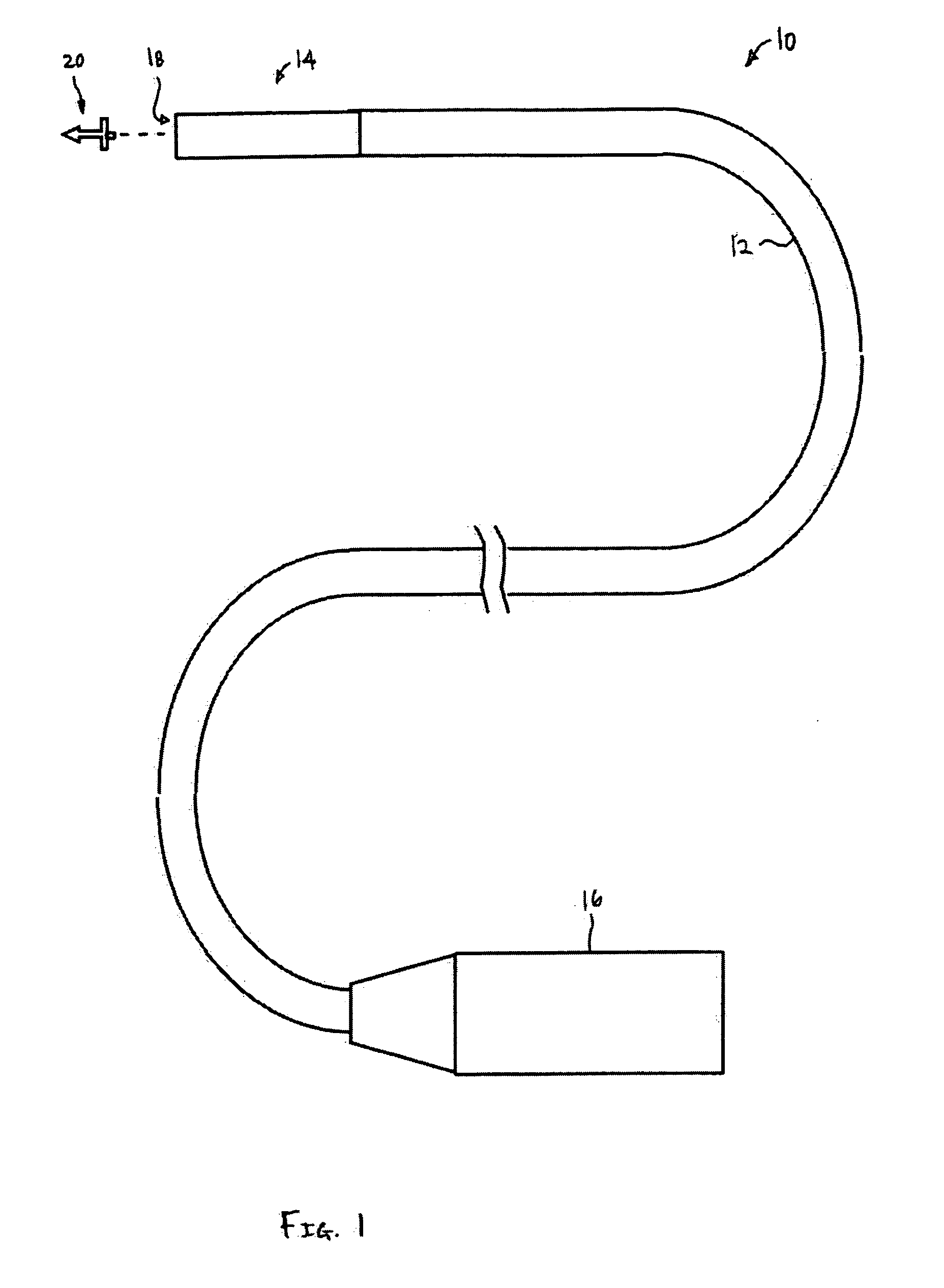
[0029] One example of an anchor delivery assembly 10 is shown in the assembly view of FIG. 1. The assembly 10 may generally have a handle assembly 16 for manipulation by a practitioner from outside the patient with a flexible elongate body 12 extending from the handle 16. The flexible elongate body 12 is generally a flexible tubular shaft which may be fabricated utilizing any number of catheter-based technologies provided that the elongate body 12 is sufficiently flexible to be advanced within the patient through the vasculature or intraluminally.

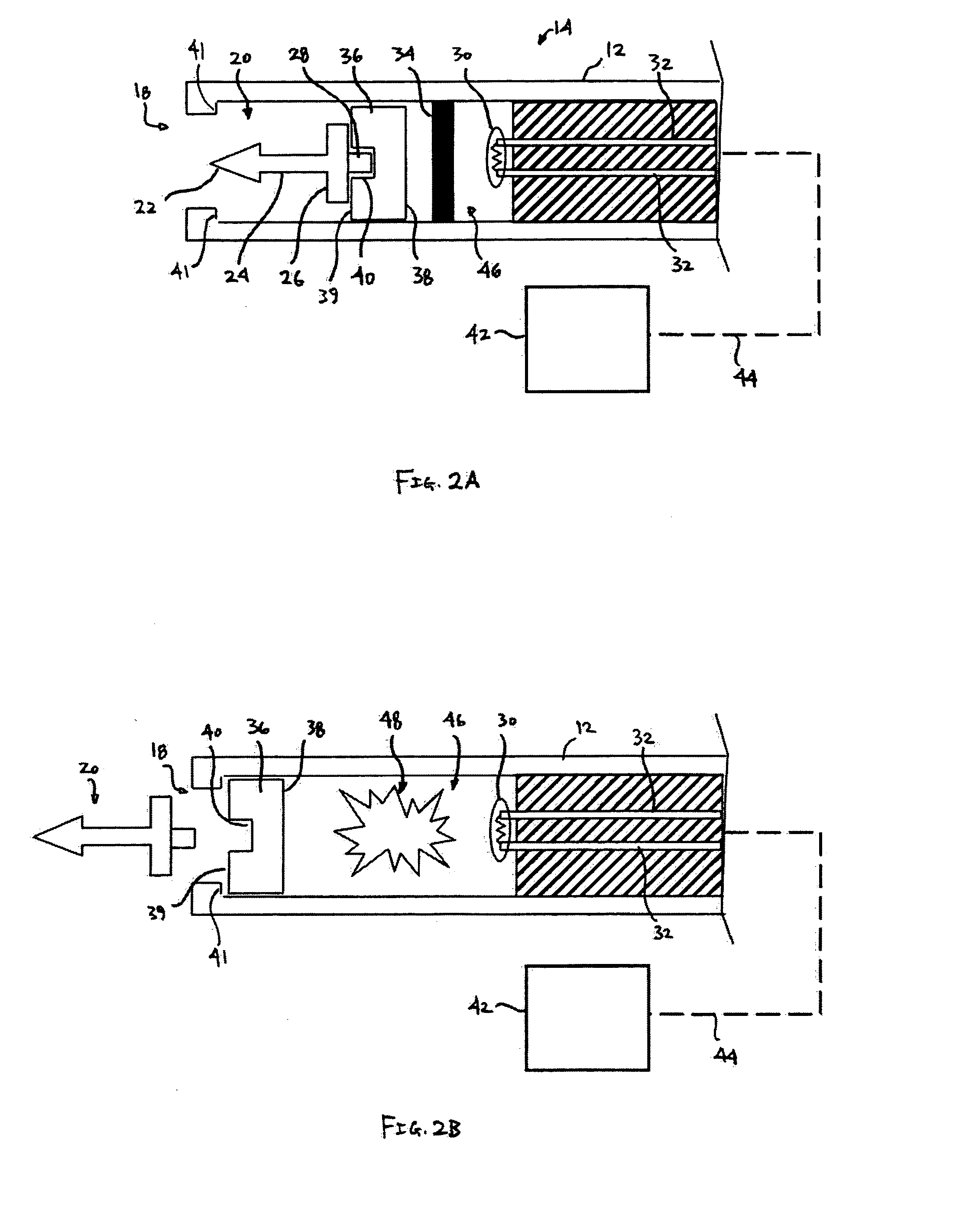
[0030] An anchor launch assembly 14 may be positioned upon the distal end of the elongate body 12 and may house one or more tissue anchors 20 which may be deployed or ejected at high speed through distal opening 18 defined in the distal end of the anchor launch assembly 14. The one or more tissue anchors 20 may be ejected by manipulating a control mechanism located on handle 16 from outside the patient body.

[0031] In one example of use, t...


PUM


Abstract

A kinetic anchoring deployment system utilizing a high-impulse, high-velocity anchor launching mechanism is described herein. The assembly generally has a handle, a flexible elongate body, and a launch assembly thereupon. The launch assembly uses a number of different mechanisms for creating a high-impulse shock wave for launching a carriage carrying a tissue anchor, e.g., combustible materials, rapid vaporization of a fluid, hydraulic energy transmission, laser energy, compression springs, electromagnetic energy, etc. The deployment system may be advanced intravascularly and / or intraluminally within a patient body for treating a number of different indications.

Description

FIELD OF THE INVENTION [0001] The present invention relates generally to medical devices used for intravascular or intraluminal anchor placement within a body. More particularly, the present invention relates to apparatus and methods for intravascularly and / or intraluminally deploying tissue anchors or for rapidly piercing tissue regions, for instance, for taking biopsy samples within a body utilizing a rapid anchor delivery system. BACKGROUND OF THE INVENTION [0002] The treatment of tissue within a body is generally made difficult especially when instruments are advanced and positioned via an intravascular or intraluminal approach. For instance, procedures which require access within the chambers of a patient's heart typically involve introducing a flexible catheter through a percutaneous incision and threading the catheter through the patient's vasculature until access to the appropriate chamber is acquired. [0003] However, once within the heart chamber, a procedure such as delive...

Claims


Application Information

Patent Timeline
20 Sep 2007
Publication
US20070219565A1
IPC
A61B17/10
CPC
A61B10/0275; A61B17/0401; A61B17/0682; A61B2017/922; A61B2017/00544; A61B2017/00876; A61B2017/0409; A61B2010/0208
Inventors
SAADAT, VAHID