

Expandable and adjustable lordosis interbody fusion system
- Summary
- Abstract
- Description
- Claims
- Application Information
AI Technical Summary
Benefits of technology
Problems solved by technology
Method used
Image

Examples
Embodiment Construction
.
BRIEF DESCRIPTION OF THE DRAWINGS FIGURES
[0017]An embodiment of the present invention is described herein with reference to the following drawing figures, with greater emphasis being placed on clarity rather than scale:
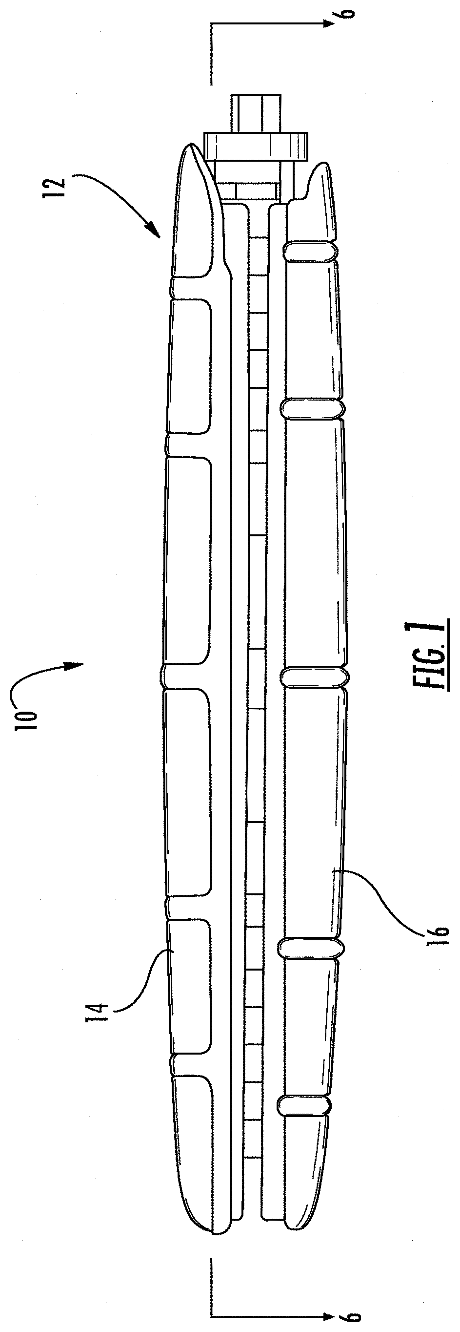
[0018]FIG. 1 is a view in side elevation from the side of the expandable shell device.
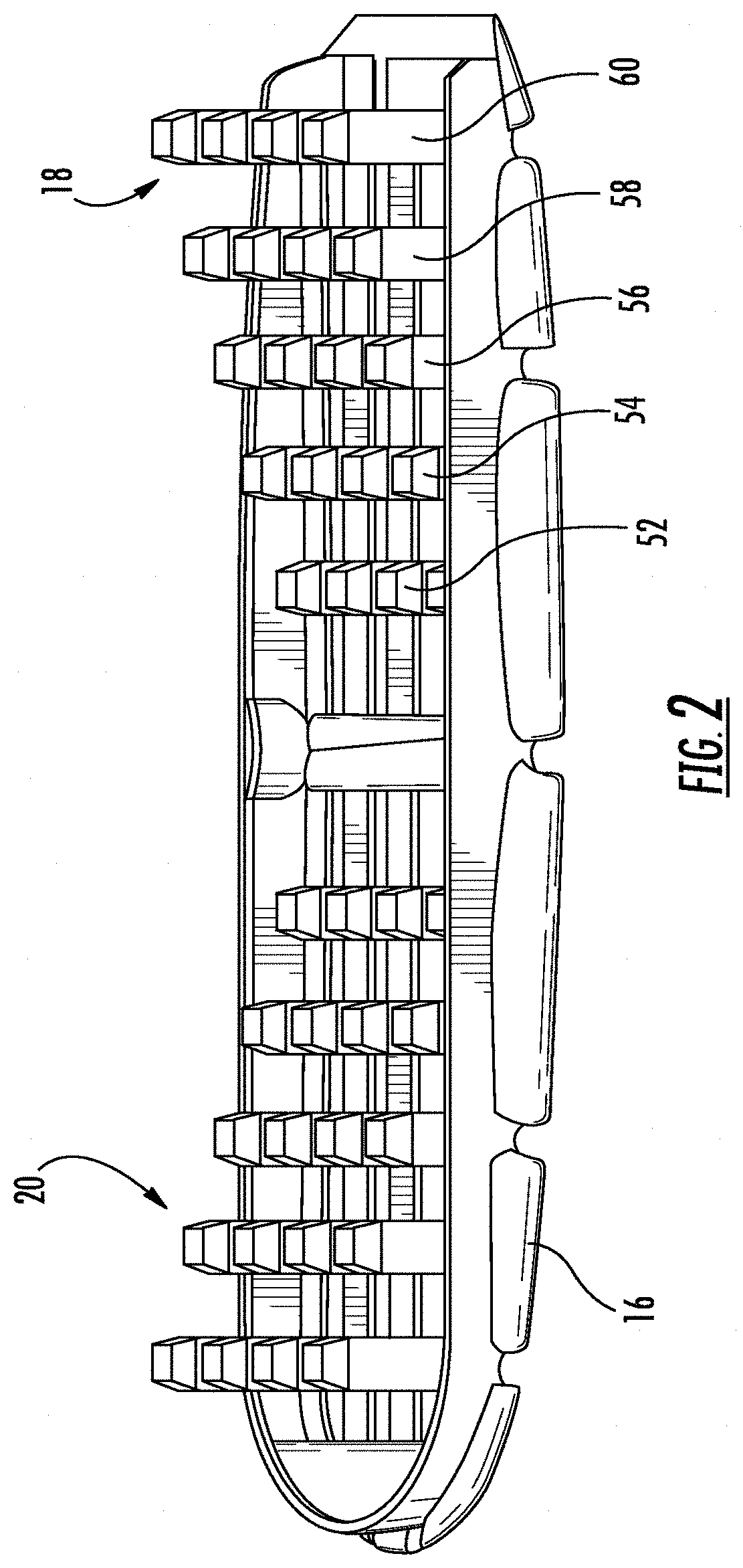
[0019]FIG. 2 is a perspective view of a bottom section of the expandable shell.
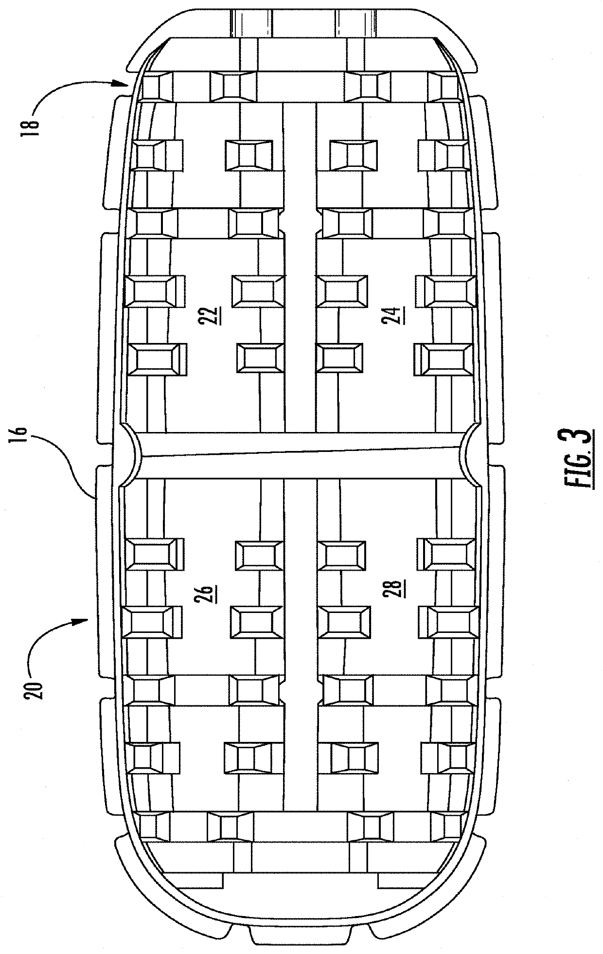
[0020]FIG. 3 is a top plan view of the bottom section of the expandable shell.
[0021]FIG. 4 is a top plan view of the expandable shell device.
[0022]FIG. 5 is a perspective view of a tapered external helical threaded member.
[0023]FIG. 5A is a view in side elevation from the side of the tapered external helical threaded member.
[0024]FIG. 5B is a view in side elevation from the front of the tapered external helical threaded member.
[0025]FIG. 6 is a cross-sectional view of the device taken along lines 6-6 in
[0026]FIG. 1.
[0027]FIGS. 7A-7C are a series of views in side elevation of the device as it undergoes exp...
PUM
 Abstract
Description
Claims
Application Information