
Beverage brewing apparatus with a filter carrier receiver

Active Publication Date: 2011-09-15
HAMILTON BEACH BRANDS
View PDF1 Cites 17 Cited by
  • Summary
  • Abstract
  • Description
  • Claims
  • Application Information

AI Technical Summary

Benefits of technology

[0015]Once actuated to the closed position, the subject locking mechanism continues to clamp and seal the carrier to a seal surface until the user selectively disengages the locking mechanism. With the locking mechanism disengaged, the carrier withdraws from the seal surface under gravitational force. In one embodiment, a resilient body or material, such as a spring, expandable foam, or other resilient material, is included to facilitate the separation of the filter carrier from the seal surface. The user does not apply any force to separate the filter carrier from the seal surface. Once in the free position, the filter carrier can be removed from the beverage maker without rotating the filter carrier. The user withdraws the filter carrier along the same linear axis as was employed to insert the carrier into the front face of the receiver.
[0020]As will be understood better in view of the subject figures and detailed description, the apparatus and method as disclosed herein facilitates the insertion of a filter carrier into a beverage brewer relative to conventional filter carriers. Once inserted, the carrier is supported at all times so as to prevent accidental separation of the filter carrier from the beverage maker, including during a brew cycle.
[0021]In addition, because the filter carrier is inserted into the front face of a receiver, the user may easily ascertain the proper alignment of the filter carrier with the receiver. Moreover, the new locking mechanism disclosed here remains in the locked or closed position until a user actuates the locking mechanism away from the closed position.
[0022]The subject apparatus and method also facilitates the removal of the filter carrier from a beverage maker following a brew cycle relative to conventional bayonet-style locking filter carriers. Whereas conventional filter carriers can be difficult to disengage following a brew cycle, particularly where pressurized fluid is employed, the subject locking mechanism releases the filter carrier from the seal prior to the user attempting to remove the filter carrier from the beverage maker. The user actuates the lever back to the first, open position. The drive cam moves to the first, open position thereby releasing the slide cam. The lift cams push the slide cam back thereby allowing the lift cams to lower away from the sealing surface. In one embodiment, a resilient member or material may apply a downward force on the lift cams. The lift cams engage the filter carrier during the downward motion of the lift cam(s) to ensure the carrier separates from the sealing surface. The filter carrier can then be removed by linearly removing the filter carrier from the locking mechanism. The user does not apply force to unlock or unseal the filter carrier from the beverage maker.
[0023]In short, a filter carrier and locking mechanism in accordance with the subject disclosure efficiently addresses at least one of the above or other shortcomings of conventional filter carriers and locking mechanisms. The construction and method disclosed herein facilitates the insertion and removal of the filter carrier to a beverage maker. Moreover, the construction prevents the complete separation of the filter carrier from the beverage maker during a brew cycle even if the carrier is in an unsealed or free position.

Problems solved by technology

There are recognized problems with this conventional construction.
First, the user is unable to determine whether the filter carrier is in the proper alignment to insert the carrier into the brew head because the brew head's inclined planes are on an internal diameter or surface that is not visible to the user.
Since this alignment cannot be confirmed prior to inserting the filter carrier, the user must often make several attempts to properly align the carrier so that it may be inserted into the brew head.
Basically, the insertion of the carrier requires trial and error.
This mechanism can be frustrating for a user and may lead to spilling the contents of the carrier reservoir or otherwise not properly securing the filter carrier.
In addition, it is often unclear to the user how far the carrier should be rotated to ensure a proper seal while avoiding damage to the brew head or carrier caused by too much force.
If the user fails to properly and fully lock the carrier, the seal between the carrier and the brew head may leak when liquid, pressurized gas, or pressurized fluid is introduced to the carrier from the beverage maker.
On the other hand, applying too much rotational force can permanently damage the carrier, the brew head, or the seal between the two.
It has also been noted, as in U.S. Pat. No. 5,642,656, that pressurized beverage makers can make the removal of conventional bayonet-coupling carriers difficult.
The force between the conventional bayonet connecting elements caused by the relatively high pressure produced by the beverage maker is so great that the filter carrier practically cannot be released after a brew cycle.
This can be a further source of frustration for the user of a conventional filter carrier.
Bayonet locking mechanisms interfere with the user's ability to clean the seal area.
It might also preclude or reduce the possibility of the carrier disengaging from the beverage maker during operation.

Method used


Image

  • Beverage brewing apparatus with a filter carrier receiver
  • Beverage brewing apparatus with a filter carrier receiver
  • Beverage brewing apparatus with a filter carrier receiver

Examples


Embodiment Construction

[0032]As will be described in detail herein, the subject apparatus and method can improve the insertion of a filter carrier into, sealing of a filter carrier to, and removal of a filter carrier from a beverage brewer. There are possible and foreseen variations of the subject filter carrier, receiver, and a locking mechanism as disclosed herein. Accordingly, the specific structure disclosed and illustrated is not a reasonable limitation of the scope of the present disclosure and claims. The following describes certain preferred embodiments of the filter carrier, receiver, locking mechanism, and a beverage maker with the same.

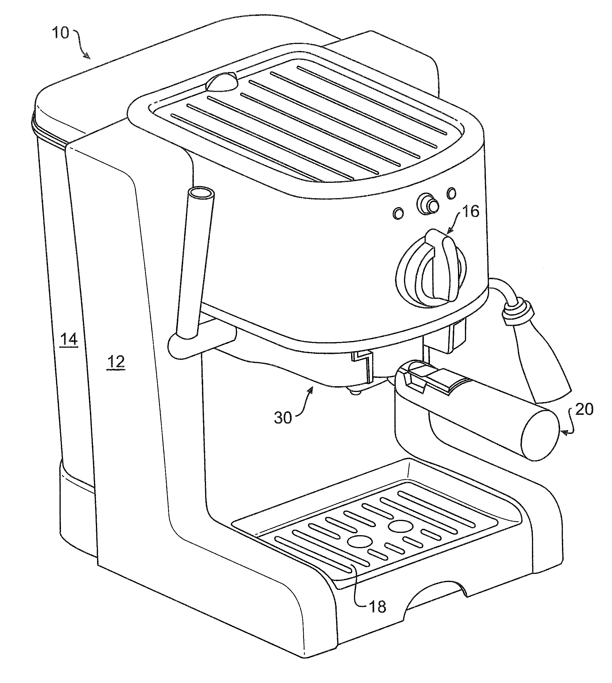
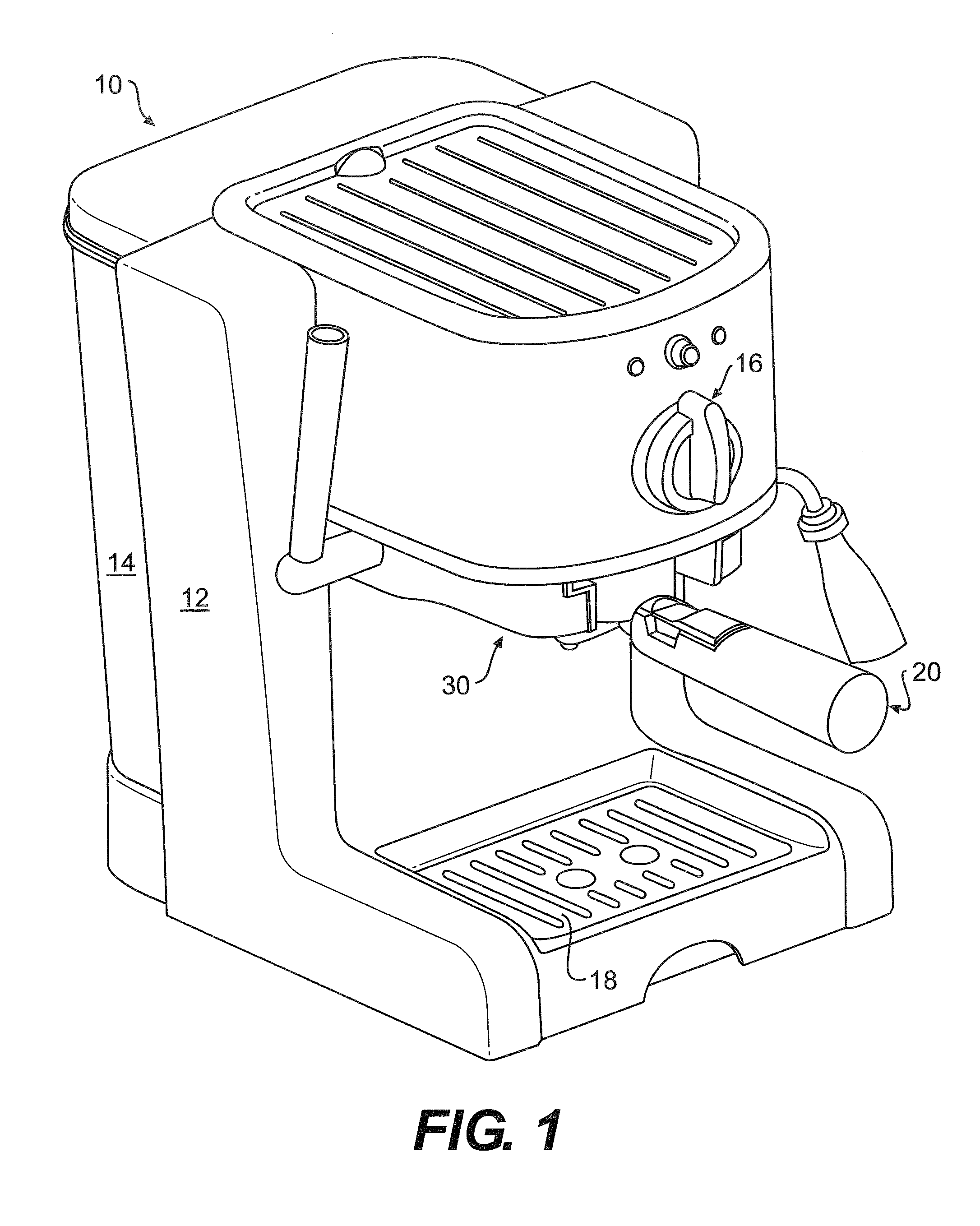
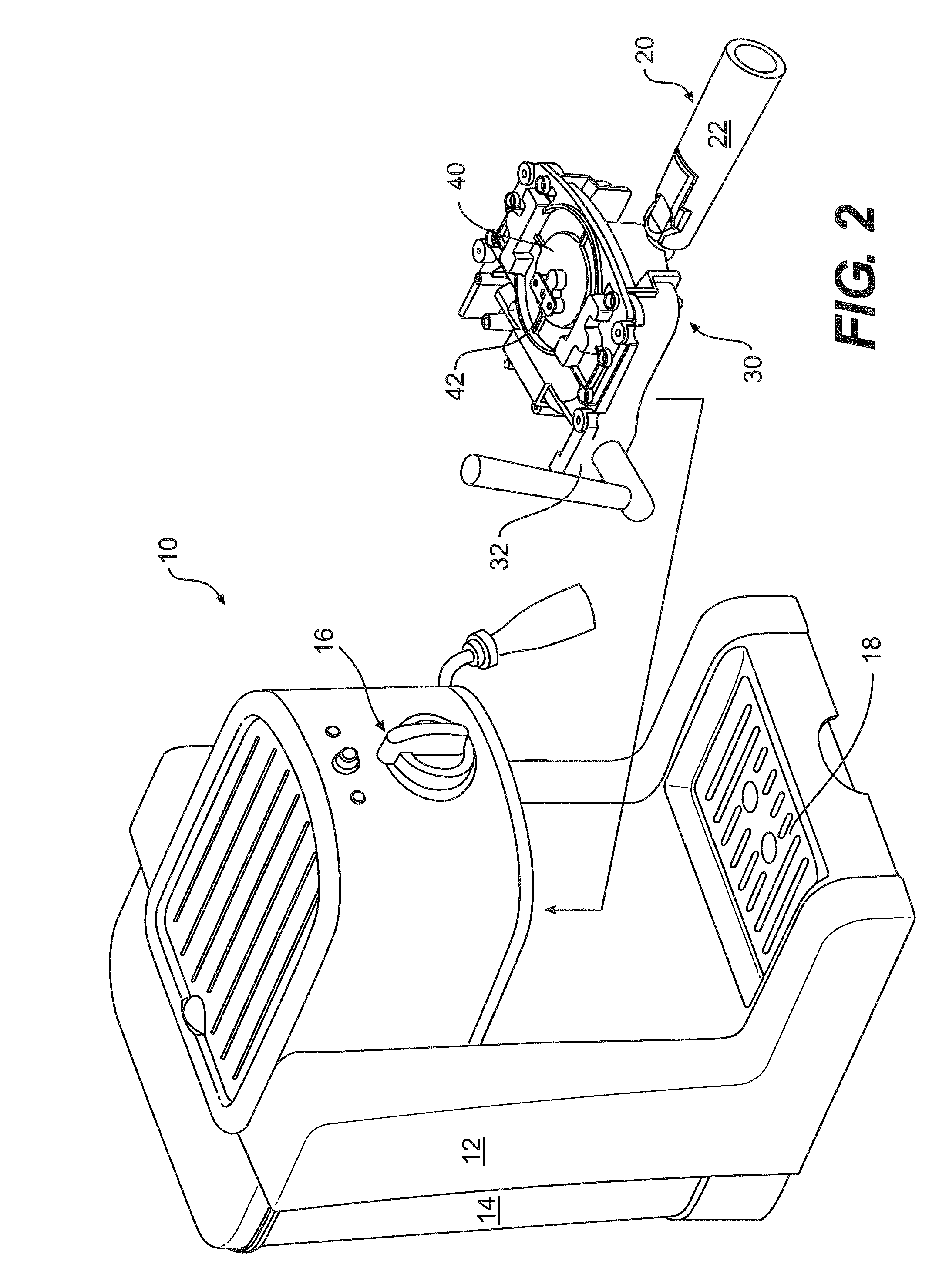
[0033]Turning first to FIGS. 1 and 2, there is illustrated a beverage maker 10 comprising a stand 12, fresh water reservoir 14, and a selectively removable filter carrier 20. The beverage maker has a front face including controls 16 as well as two sides, a top, a bottom, and a back face. Generally, the beverage maker will be placed on a countertop with the front ...


PUM


Abstract

A beverage maker is disclosed with a removable filter carrier, a receiver for the removable filter carrier, and a locking mechanism to selectively secure and seal the carrier to the beverage maker by way of lifting the carrier to engage a sealing surface. In use, the filter carrier is linearly inserted into the receiver via a front face of the beverage maker. The receiver may also include the locking mechanism. The locking mechanism includes a lever that is actuated to operate the locking mechanism. Actuation of the lever is translated to lift and clamp the filter carrier against the seal surface. In the ‘sealed’ position, the lever is selectively fixed in place until the user actuates the lever so as to release the filter carrier. In the ‘released’ position, the filter carrier is still supported by the locking mechanism but it may be selectively removed from the receiver. The locking mechanism reduces or eliminates conventional issues with securing a filter carrier to a beverage maker such as properly aligning the filter carrier so that it may be secured to the beverage maker, the filter carrier disengaging from the beverage maker during use, or not being able to remove the filter carrier after a brew cycle.

Description

FIELD OF THE DISCLOSURE [0001]The present apparatus relates to a beverage brewer comprising a removable filter carrier and a filter carrier receiver that facilitates insertion and removal of the filter carrier. The filter carrier is linearly inserted into the face of the receiver. In one embodiment, the receiver further comprises a lever-actuated locking mechanism to secure and seal the filter carrier to a seal surface of the beverage maker. The locking mechanism translates the actuation of the lever to vertically lift the filter carrier.BACKGROUND [0002]Certain beverage brewers, such as espresso makers, include removable filter holders / carriers that are selectively locked in place on the beverage brewer. The filter carriers include a handle and a reservoir containing a filter and an infusible material. Conventional filter holders are connected to the beverage brewer by way of rotating the filter holder to engage a bayonet coupling as illustrated, for example, by U.S. Pat. Nos. 4,64...

Claims


Application Information

Patent Timeline
IPC IPC(8): A47J31/06A23L2/38
CPCA23L2/39A47J31/446A47J31/4467A47J31/3666
Inventor STAR, WILLIAM D.ROMANDY, MARK K.
Owner HAMILTON BEACH BRANDS
Learn More