Electrical apparatus

A technology for electrical devices and working positions, applied in the direction of electrical components, substation/switch layout details, etc., to achieve a simple effect in terms of structure

Inactive Publication Date: 2010-05-26
MOELLER GEBAUDEAUTOMATION KG
View PDF5 Cites 0 Cited by
  • Summary
  • Abstract
  • Description
  • Claims
  • Application Information

AI Technical Summary

Problems solved by technology

[0007] A disadvantage of the devices according to EP 1 058 360A and DE 87 04 865U is that they can only be mounted and / or removed on a busbar arranged on the side of the movable fixing mechanism

Method used


Image

  • Electrical apparatus
  • Electrical apparatus
  • Electrical apparatus

Examples


Embodiment Construction

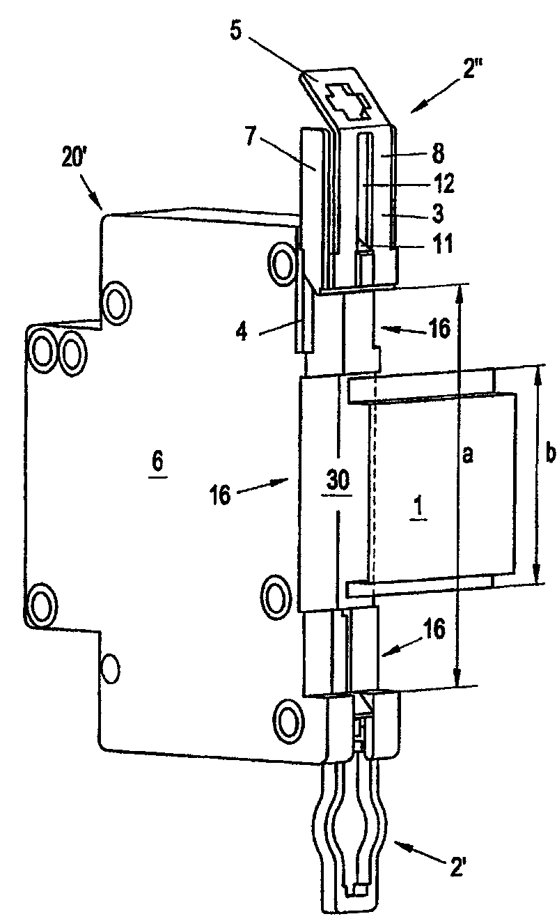
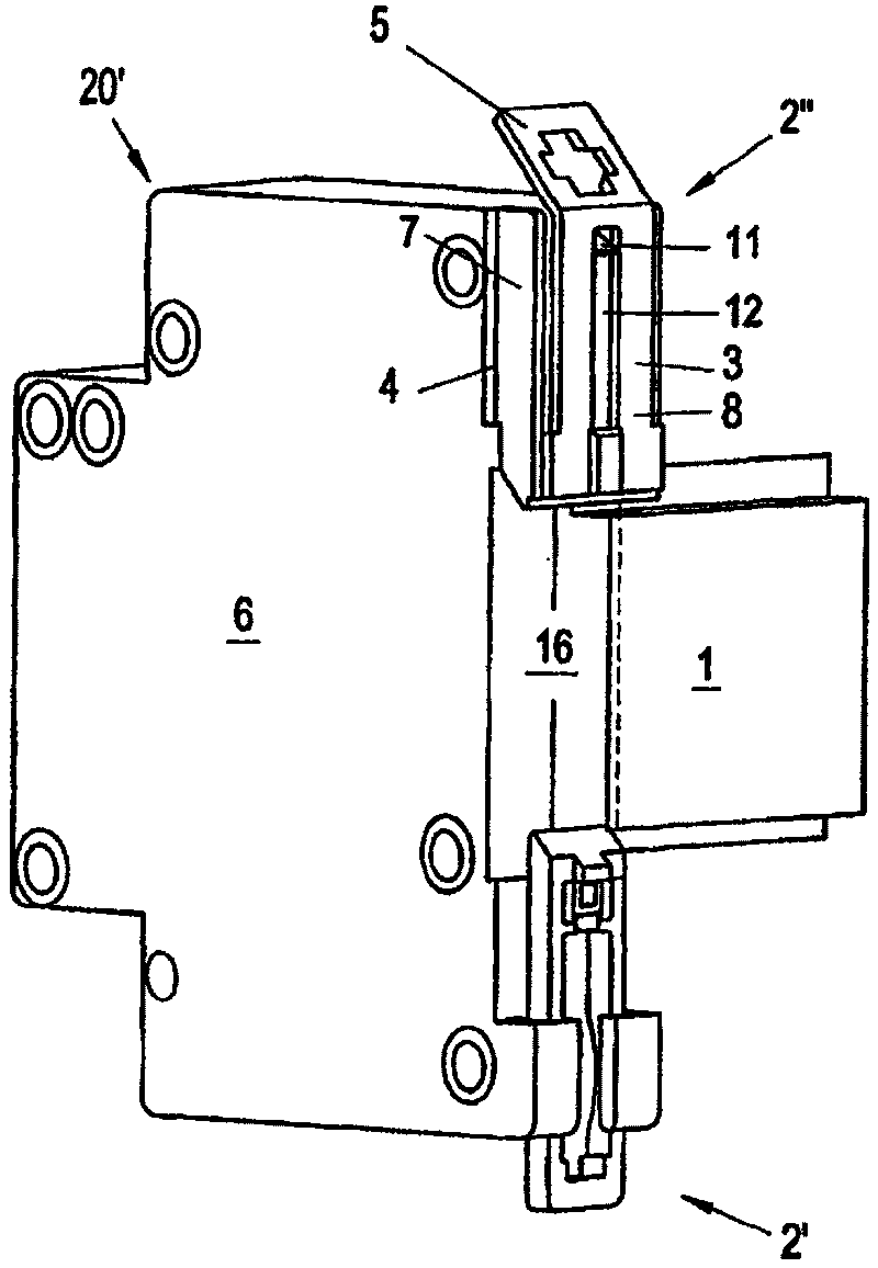
[0038] like figure 1 and 2 As shown, on the device outer wall 6 of an electrical device, such as a line protective switch, a first fixing mechanism 2' and a second fixing mechanism 2" are arranged radially to each other on the respective end regions of the narrow faces. The first fixing Mechanism 2' is prior art, for example, is made up of the fast fixing mechanism of electric device, is used for being installed on the support rail 1 that cross-section is hat shape, and described support rail has elastic locator, and it can be fixed at desired position. It moves on the side guide mechanism of the device and has a symmetrical frame structure around its longitudinal axis, in which there is a stop position of a positioner. But this can be moved transversely to the support rail 1 into a first fixed position in a fixed position Mechanism 2'—since its specific design is not relevant to the invention—can be designed arbitrarily.

[0039] The second fixing mechanism 2 " can be moved...


PUM


Abstract

The invention concerns an electrical apparatus (20) comprising a housing (20') having a on its rear surface a recess (16) for receiving a mounting rail (1), the dimension (a) of the recess (16) beinggreater than the dimension (b) of the mounting rail (1), viewed respectively in the vertical axis direction of the apparatus (20), and retaining devices (2', 2'') capable of being inserted in the inner space of the recess (16) and interlocked in their fixing position. At least one of the retaining devices is maintained in its working position elastically projecting into the inner space of the recess (16) towards its inactive position clearing the inner space. The apparatus (20) is provided, in its upper zone and in its lower zone, with clamping devices (31) wherein can be introduced connectingelements of collecting bars (21, 21a, 23) in a plane almost parallel to the mounting rail (1) and at a predefined insertion depth (t). The invention aims at facilitating mounting and dismounting of such an electrical apparatus. Therefor, the dimension (a) of the recess (16) is greater than the dimension (b) of the mounting rail by at least the sum of the insertion depth (t) for the connecting elements of the clamping devices (31) provided at the upper zone and the lower zone, viewed respectively in the direction of the vertical axis of the apparatus.

Description

technical field [0001] The invention relates to an electrical device. Background technique [0002] Such a device is disclosed, for example, in FR-A-2 716 042. In this disclosed device there is provided an elevator terminal for accommodating busbar terminal elements, the opening stroke of which is distributed perpendicular to the support rail minus the dimension of the terminal element in the direction of the terminal opening stroke, at least as large as the hat-shaped support rail in cross section The depth is the same size. In this respect, the insertion depth of the busbar is significantly greater than the difference between the width of the device housing recess and the width of the support rail. [0003] In this disclosed solution, when the device is removed from the support rail, it is therefore necessary to completely open the terminals for receiving the busbars and to move the two The fastening mechanism feeds into the stationary device outside the free space of t...

Claims


Application Information

Patent Timeline
Patent Type & Authority Patents(China)
IPC IPC(8): H02B1/052
CPCH02B1/0523H02B1/052
Inventor E·汉麻梅亚
Owner MOELLER GEBAUDEAUTOMATION KG
Why Eureka
Try Eureka