Round multi-fiber cable assembly and a method of forming same

a multi-fiber cable and assembly technology, applied in the direction of optics, fibre mechanical structures, instruments, etc., can solve the problems of low crush resistance of flat cable assemblies, damage to ribbons, and the ability of flat cable assemblies to only be bent along the flat side, so as to achieve the effect of resisting damag

Inactive Publication Date: 2006-03-02
MOLEX INC
View PDF6 Cites 11 Cited by
  • Summary
  • Abstract
  • Description
  • Claims
  • Application Information

AI Technical Summary

Benefits of technology

[0010] An object of the present invention is to provide a method which uses several relatively inexpensive parts to enable round multi-fiber cables to be processed such that the ends of the cables may be terminated to ...

Problems solved by technology

Flat cable assemblies have several disadvantages in cable routing.
First, the flat cable assembly can only be bent along the flat side.
Any attempt to bend the flat cable assembly in the other direction damages the ribbons.
Third, the flat cable assembly has a low crush resistance since the jacket is thin and does not provide enough protection to the ribbons.
As round multi-fiber cables were only invented within the last few years, they have not ...

Method used


Image

  • Round multi-fiber cable assembly and a method of forming same
  • Round multi-fiber cable assembly and a method of forming same
  • Round multi-fiber cable assembly and a method of forming same

Examples


Embodiment Construction

[0025] While the invention may be susceptible to embodiment in different forms, there is shown in the drawings, and herein will be described in detail, specific embodiments with the understanding that the present disclosure is to be considered an exemplification of the principles of the invention, and is not intended to limit the invention to that as illustrated and described herein.

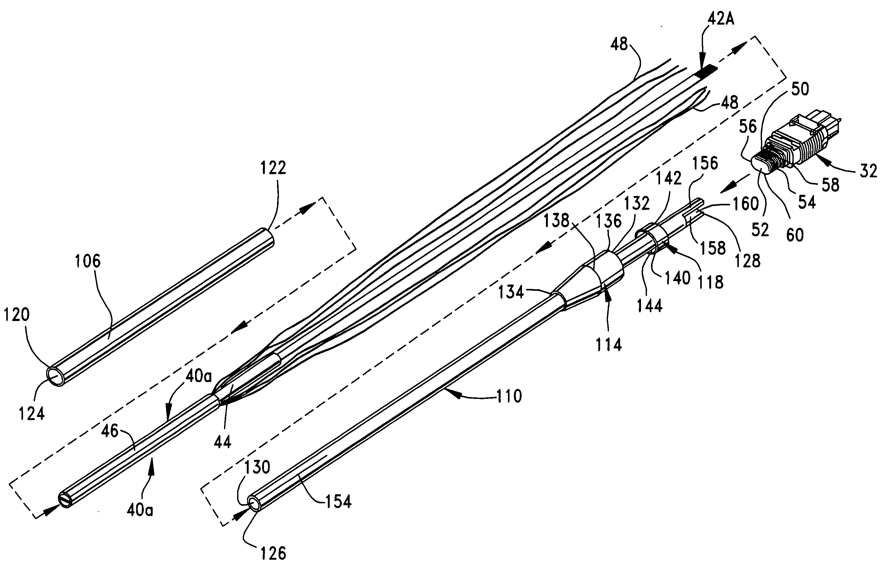
[0026] A method 100 of terminating a round multi-fiber cable 40a, 40b to a multi-fiber connector 32 which accepts ribbon cables 20, in order to form a round multi-fiber cable assembly 200, will now be discussed with regard to FIGS. 5-13D. The steps of the method 100 are best illustrated in FIGS. 13A-13D.

[0027] In step 102, either the round multi-fiber cable 40a or the round multi-fiber cable 40b is provided. The method 100 will be further discussed herein as though the round multi-fiber cable 40a has been provided. As illustrated in FIG. 5, the round multi-fiber cable 40a contains two 24-fiber ribbons ...


PUM


Abstract

A method of forming a round multi-fiber cable assembly is provided which includes the following steps: providing a round multi-fiber cable, a heat shrinkable tube, a tubing, a boot, a crimp tubing, and a multi-fiber connector; threading the heat shrinkable tube onto the multi-fiber cable; stripping off inner and outer jackets of the multi-fiber cable to pre-determined lengths; ribbonizing the fibers of the multi-fiber cable, if necessary; preparing the tubing as required; threading the fibers and strength members of the multi-fiber cable through the tubing; placing the boot and the crimp tubing on the tubing, assembling the multi-fiber connector to the ribbon; crimping the crimp tubing around the tubing, the strength members and the multi-fiber connector; heat shrinking the heat-shrinkable tubing to the round multi-fiber cable and the tubing; and sliding the boot to attach it to the multi-fiber connector to provide a round multi-fiber cable assembly.

Description

FIELD OF THE INVENTION [0001] The invention relates to connectorization, or termination, of multi-fiber cables for fiber optic communications. More particularly, the invention relates to termination of round, jacketed multi-fiber cables to connectors that accept ribbon cables, such as the MTO connector. BACKGROUND OF THE INVENTION [0002] Ribbon cables contain many fibers that are embedded in a plastic material in parallel, forming a flat ribbon-like structure. Ribbon cables are used directly in friendly environments without any further protection or reinforcement. For many other applications, one or more ribbons are packaged with strength members, such as kevlar, in a PVC jacket for protection and easy handling. Such a ribbon cable 20 is illustrated in FIG. 1. The ribbon cable 20 contains two 12-fiber ribbons 22, which are formed by fibers 24 embedded in coatings 26. The 12-fiber ribbons 22 are packaged within the jacket 28 with strands 30 of strength members. The jacket 28 is a tub...

Claims


Application Information

Patent Timeline
IPC IPC(8): G02B6/36
CPCG02B6/3885G02B6/4476G02B6/3887G02B6/3888G02B6/3889
Inventor CHEN, WENZONGSCHILTZ, THOMASGROIS, IGOR
Owner MOLEX INC
Why Eureka
Try Eureka