Pseudo 3D image creation device, pseudo 3D image creation method, and pseudo 3D image display system

a 3d image and creation method technology, applied in the field of pseudo 3d image creation methods, and pseudo 3d image display systems, can solve the problems of difficult automatic estimation of reliable depth without editing, difficult automatic determination, and difficult automatic composition of correct depth structure models for making images

Active Publication Date: 2006-03-23
JVC KENWOOD CORP A CORP OF JAPAN
View PDF0 Cites 53 Cited by
  • Summary
  • Abstract
  • Description
  • Claims
  • Application Information

AI Technical Summary

Benefits of technology

[0017] One of the advantages of using basic depth models is that expressing an actual three-dimensional scene, whose structure is actually complex, using a curved surface or a flat surface represented by relatively simple expressions makes it possible to process a visual extensity (a perspective effect) in a simple calculation that does not involve a motion estimation process or a vanishing point determination process.
[0018] For example, though the first basic depth model type that indicates a regular sphere concave surface is used as the base, the composition ratio is changed as follow. For example, the activity in the top part of the screen is low, the ratio of the second bas

Problems solved by technology

However, because it is difficult to automatically estimate a reliable depth without editing and only from the motion, a pseudo 3D image creation device and a pseudo 3D image creation method for making this editing easy are also known (for example, see Japanese Patent Laid-Open Publication No.
However, there are problems with the conventional pseudo 3D image creation devices and the pseudo 3D image creation methods described above in that it is difficult to automatically determine a vanishing point for various images, in that perspective structure estimation is not always suitable for all received scenes, and in that, even if perspective structure estimation is suitable, i

Method used


Image

  • Pseudo 3D image creation device, pseudo 3D image creation method, and pseudo 3D image display system
  • Pseudo 3D image creation device, pseudo 3D image creation method, and pseudo 3D image display system
  • Pseudo 3D image creation device, pseudo 3D image creation method, and pseudo 3D image display system

Examples


Embodiment Construction

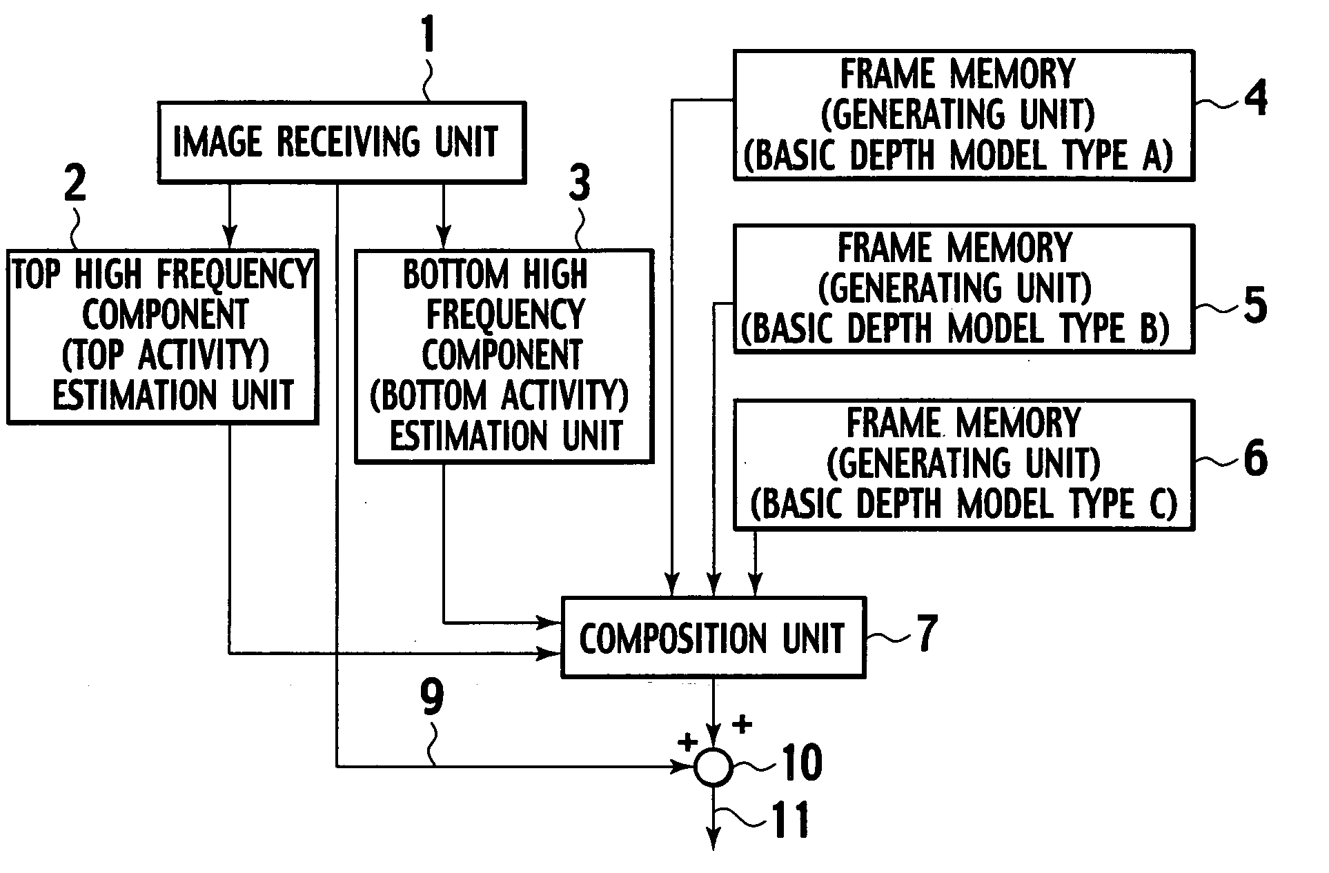
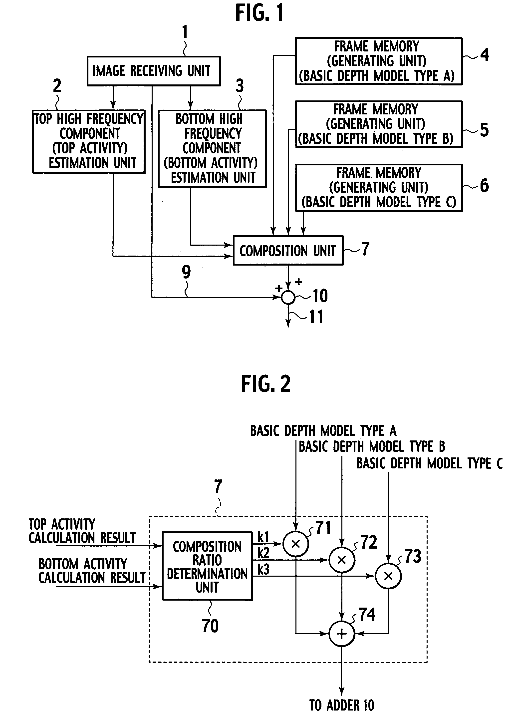
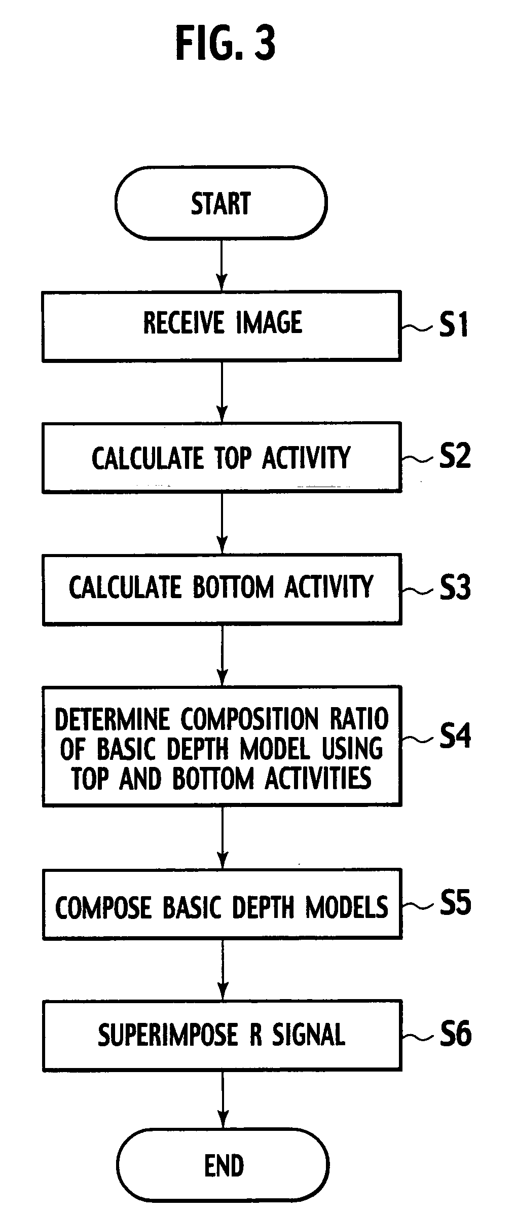
[0044] An embodiment according to the present invention will be described below with reference to the drawings. FIG. 1 is a block diagram showing one embodiment of a pseudo 3D image creation device according to the present invention. FIG. 2 is a block diagram showing one embodiment of a composition unit shown in FIG. 1. FIG. 3 is a flowchart showing one embodiment of a pseudo 3D image creation method according to the present invention.

[0045] Referring to FIG. 1, the pseudo 3D image creation device in this embodiment comprises an image receiving unit 1 that receives a non-3D image to be converted to a pseudo 3D image; a top high frequency component estimation unit 2 that calculates “a high region component estimation value of about top 20% part (top high frequency component estimation value or top activity)” of a non-3D image received from the image receiving unit 1; a bottom high frequency component estimation unit 3 that calculates “a high region component estimation value of abou...


PUM


Abstract

To allow any image to be viewed naturally and to determine a scene structure as close to a real object as possible, frame memories store therein three types of basic depth models indicating the depth values of three basic types of scene structures, one basic depth model for each scene structure. A composition ratio is determined according to the high frequency component estimation values or activity values of the luminance signal of a received non-3D image that are received from a top activity unit and a bottom activity unit and, based on the composition ratio, the three types of basic depth models are composed. The R signal of the non-3D image is superimposed on the composed basic depth model in an adder to produce final depth estimation data.

Description

BACKGROUND OF THE INVENTION [0001] 1. Field of the Invention [0002] The present invention relates to a pseudo 3D image creation device, a pseudo 3D image creation method, and a pseudo 3D image display system. More particularly, the present invention relates to a pseudo 3D image creation device and a pseudo 3D image creation method for creating a pseudo 3D image from a regular still image or moving image, that is, an image (a non-3D image) having depth information supplied neither explicitly nor, unlike a stereo image, implicitly, and to a pseudo 3D image display system that displays a created pseudo 3D image. [0003] 2. Description of the Related Art [0004] To allow a non-3D image to be viewed as a 3D image in a 3D display system, a pseudo 3D image is created from a regular still image or moving image, that is, an image (a non-3D image) having depth information supplied neither explicitly nor, unlike a stereo image, implicitly. In addition to making an image to be viewed as a 3D imag...

Claims


Application Information

Patent Timeline
IPC IPC(8): G06T15/00G06T15/40
CPCH04N13/026G06T7/0051G06T7/50H04N13/261
Inventor YAMADA, KUNIO
Owner JVC KENWOOD CORP A CORP OF JAPAN
Why Eureka
Try Eureka