Liquid crystal display panel and liquid crystal display device

a liquid crystal display panel and display device technology, applied in optics, non-linear optics, instruments, etc., can solve the problems of slow propagation of liquid crystal alignment, inability to have a sufficient response characteristic, and productivity drop, and achieve stable liquid crystal alignment, high display response speed, and excellent display quality

Inactive Publication Date: 2006-03-30
SHARP KK
View PDF15 Cites 7 Cited by
  • Summary
  • Abstract
  • Description
  • Claims
  • Application Information

AI Technical Summary

Benefits of technology

[0016] According to another aspect of the present invention, provided is a liquid crystal display device equipped with the above-described liquid crystal panel. By this aspect of the present invention, a liquid crystal display device with stable liquid crystal alignment, excellent display quality and high display response speed is obtained.

Problems solved by technology

In addition, in this technology, it is not necessary to perform a rubbing treatment, which is a major cause of decrease in the productivity, owing to a body for regulating the alignment (structures having uneven portions such as protrusions, or slit patterns in an electrode) installed on the substrates to realize the multi-domain alignment.
However, even in this MVA-mode liquid crystal display device, there is a problem of not always being able to have a sufficient response characteristics.
Particularly in a lower region of the gray scale, there is a problem that the propagation of liquid crystal alignment is slower due to a lower application voltage.
However, MVA-mode liquid crystal display devices employing such bend alignment had a problem of unstable liquid crystal alignment.

Method used


Image

  • Liquid crystal display panel and liquid crystal display device
  • Liquid crystal display panel and liquid crystal display device
  • Liquid crystal display panel and liquid crystal display device

Examples


example 1

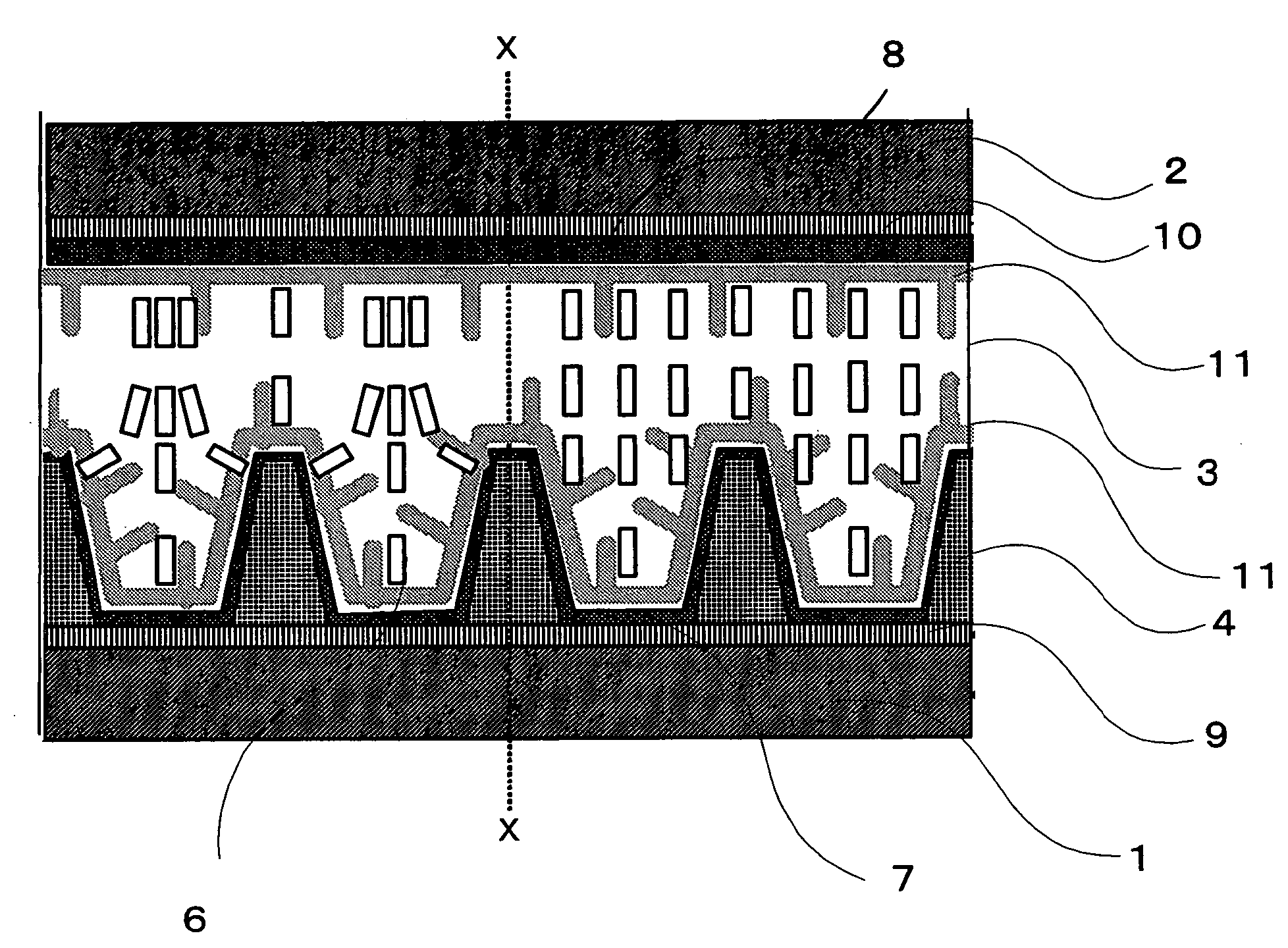
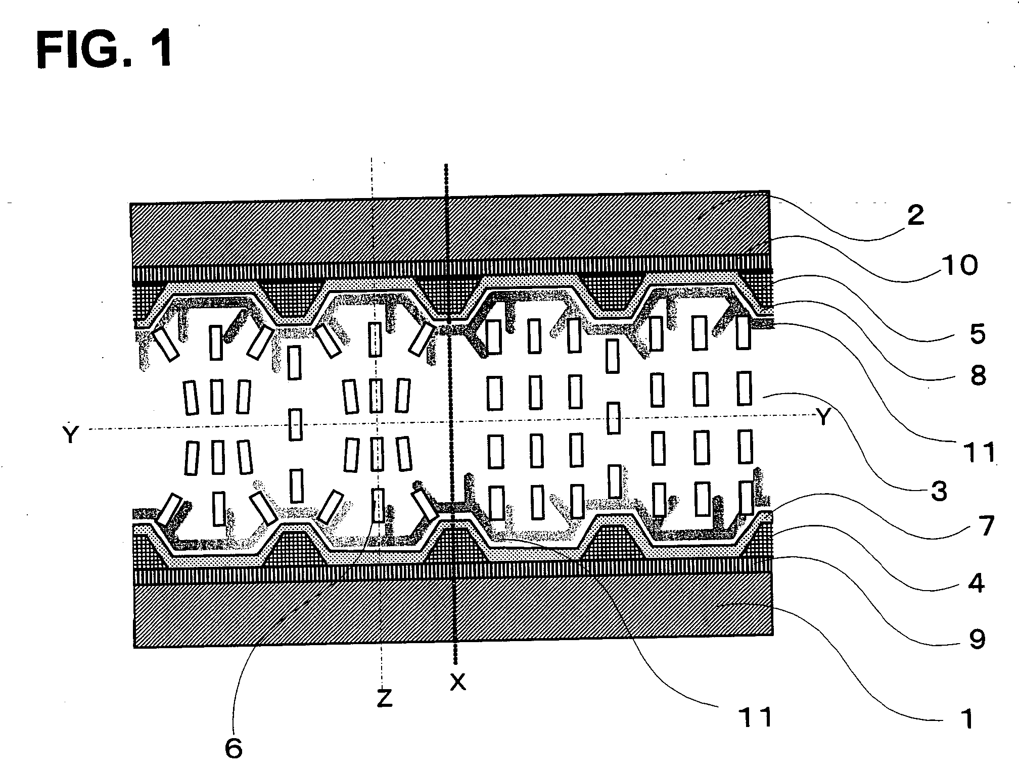
[0057] A liquid crystal panel having a constitution shown in FIGS. 1 and 2 was prepared. Vertical alignment control films were installed on the protrusions at both sides of the liquid crystal layer. A liquid crystal composition comprising a liquid crystal having a positive dielectric constant anisotropy (Δε) of 9.9, and an acrylate monomer having two acrylate groups in a molecule in an amount of 2% by weight, was disposed between the substrates.

[0058] After the liquid crystal composition had been introduced into the space controlled by a spacer, between the substrates positioned in parallel, irradiation was performed with ultraviolet rays having a wavelength of 365 nm at an intensity of 20 mW / cm2 for about 10 J / cm2, during which a voltage of 10 V was applied between the electrodes, to form a liquid crystal panel comprising the polymer according to the present invention.

[0059] The fact that the polymer was generated on the liquid crystal layer contacting surface as shown in FIG. 1 ...

example 2

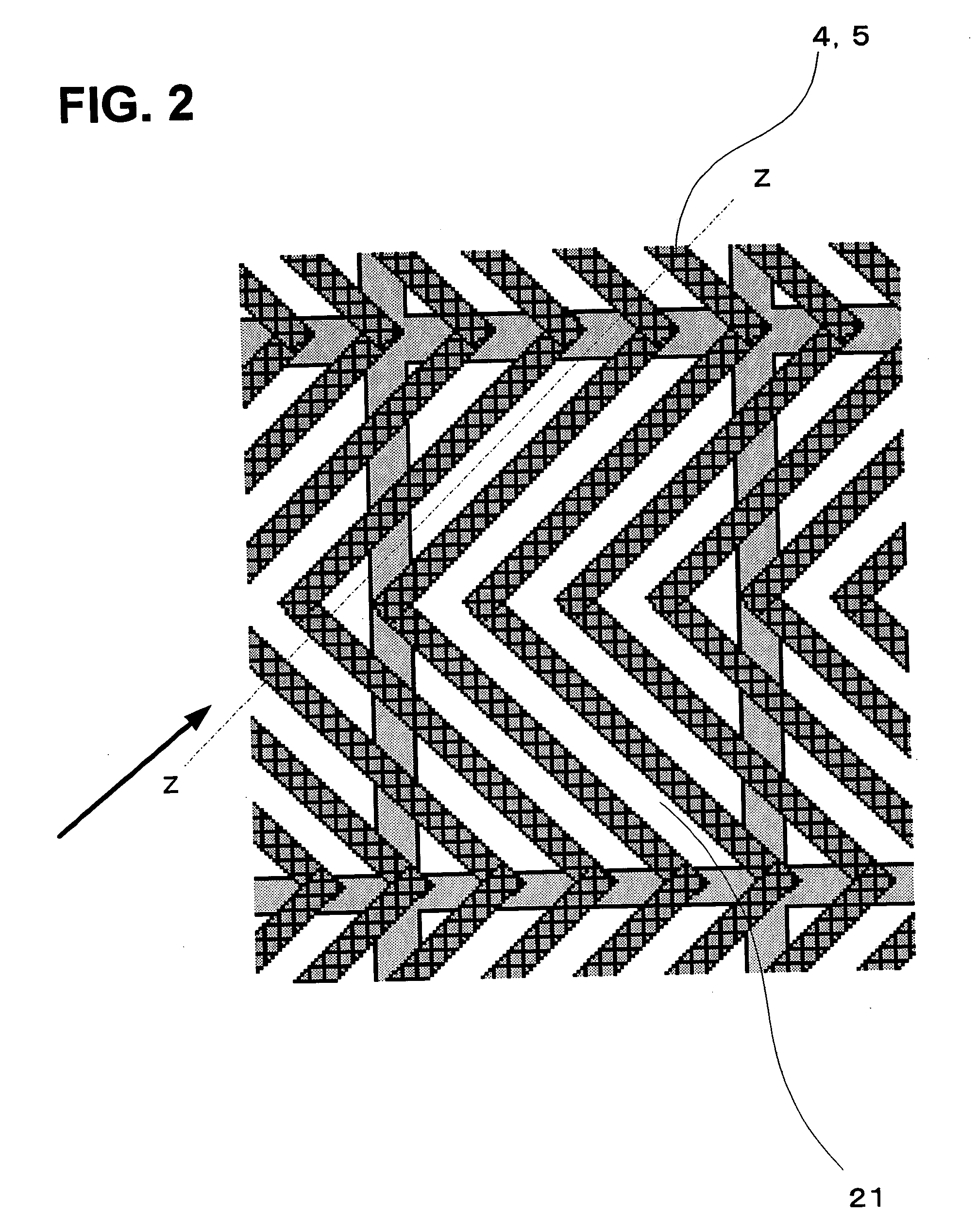
[0063]FIG. 4 is the same as FIG. 1, except that the protrusions were formed only on one side of the liquid crystal layer, and the height of the protrusions was 6 μm. The pattern of the protrusions when seen along the direction perpendicular to the substrate surface was the same as the patterns in FIG. 2.

[0064] Since the protrusions were present only on one of the two liquid crystal layer contacting surfaces, it was possible to make the alignment of the liquid crystal molecules substantially symmetrical to each other about a certain surface perpendicular to the substrate.

[0065] By installing protrusions only on one side as described in this example, the production is simplified, compared with a case in which structures are installed on both sides.

[0066] Although the protrusions were installed only on one side of the liquid crystal layer in this example, it was possible to further facilitate the bend alignment by making the slope of the protrusions longer, resulting in high display...

example 3

[0067]FIG. 3 is the same as FIG. 1, except that no vertical alignment control films were used, the height of the protrusions was 4 μm, and the constitution of the liquid crystal composition was changed as described below. The pattern of the protrusions when seen along the direction perpendicular to the substrate surface was the same as the patterns in FIG. 2. The liquid crystal composition was prepared by adding 0.3% by weight of an acrylate monomer having two acrylate groups in a molecule, as well as 0.003% by weight of a polymerization initiator, to the liquid crystal. After the liquid crystal composition had been introduced into the space between the substrates controlled by a spacer, the substrate being positioned in parallel, irradiation was performed with ultraviolet rays having a wavelength of 365 nm at an intensity of 20 mW / cm2 for about 10 J / cm2, during which a voltage of 10 V was applied between the electrodes.

[0068] By this constitution, it was confirmed by the observati...


PUM

PropertyMeasurementUnit
depthaaaaaaaaaa
heightaaaaaaaaaa
widthaaaaaaaaaa

Abstract

A liquid crystal panel and a liquid crystal display device having stable liquid crystal alignment, excellent display quality, and high display response speed are obtained. In this liquid crystal panel, uneven portions for bending the alignment of liquid crystal molecules towards the direction along the substrate surface are installed on the surfaces where the liquid crystal layer contacts its adjacent layers, and the liquid crystal layer comprises a liquid crystal having a positive dielectric constant anisotropy, and a polymer obtained by subjecting a polymerizable compound in the liquid crystal layer to irradiation with active energy rays, with or without application of a voltage.

Description

CROSS-REFERENCE TO RELATED APPLICATIONS [0001] This application is based upon and claims the benefit of priority from the prior Japanese Patent Application No. 2004-278079, filed on Sep. 24, 2004, the entire contents of which are incorporated herein by reference. BACKGROUND OF THE INVENTION [0002] 1. Field of the Invention [0003] The present invention relates to an MVA (Multi-domain Vertical Alignment) mode liquid crystal display device, and particularly to an MVA-mode liquid crystal display device having high display response speed and high quality. [0004] 2. Description of the Related Art [0005] An MVA-mode liquid crystal display device (see, for example, Japanese Unexamined Patent Application Publication No. H11-242225, claims) is a liquid crystal display device for which the vertical alignment technology for realizing a high contrast and high response speed, and the multi-domain technology for realizing a wide viewing angle are combined. [0006] In an MVA-mode liquid crystal disp...

Claims


Application Information

Patent Timeline
Patent Type & Authority Applications(United States)
IPC IPC(8): G02F1/1337
CPCG02F1/133753G02F2001/13775G02F2001/133776G02F1/1395G02F1/133776G02F1/13775
Inventor TOYOOKA, YUKIKO
Owner SHARP KK
Why Eureka
Try Eureka