Utility pole and tower safety and protection device

a protection device and utility pole technology, applied in the field of utility poles, can solve the problems of utility line loss, high cost of replacement, and high cost of assembly and maintenance, and achieve the effects of reducing the loss of revenue and replacement costs, avoiding damage, and improving safety features

Inactive Publication Date: 2006-08-03
MILLER MICHAEL L MR +7
View PDF6 Cites 13 Cited by
  • Summary
  • Abstract
  • Description
  • Claims
  • Application Information

AI Technical Summary

Benefits of technology

[0008] The present invention provides a new and useful Utility Pole and Tower Safety and Protection Device which virtually eliminates the loss of revenue and replacement costs due to irreparable damage. The device provides several advantages over the prior art, including improved safety features, and easy maintenance, management, construction and control. This device overcomes the deficiencies in the prior art and teaches safety and warning measures to minimize costly and tragic loss of life and property.

Problems solved by technology

These assemblies are costly to purchase, assemble and maintain.
Historically, thousands of miles of utility lines have been lost to adverse weather and other external forces, costing enormous amounts of money to replace.
Many consumers who depend on the utility supply have been left without service for weeks at a time, resulting in huge losses of produce, dairy and other inventory and equipment.
Further, insurance companies are burdened by the large claims that result from the loss of utility services.
The prior art does not provide a means in all cases to cease the flow of power to downed conductors and transformers.
Downed conductors often result in loss of life and damage or destruction of property.
However, while there are myriad of assemblies for utility transmission systems, none provide a convenient means of selectively lowering power lines to the ground for maintenance, repair or construction.
This can be dangerous, time consuming and expensive.
In addition, the prior art does not provide for a warning signal means when lowering these dangerous power lines and apparatus, either audible or visual.
Prior art utility systems are also sensitive to resistance and heat build up in the conductors.
This results in progressively higher resistance and the inefficient transmission of current.
Heavy loads of ice and high winds and the like can cause stretching and sagging of the conductors where conductors are reduced in diameter.
This further reduces the capacity of the conductor.
Obviously, where the conductors have exceeded their limits of strain they must be replaced, at great expense.

Method used


Image

  • Utility pole and tower safety and protection device
  • Utility pole and tower safety and protection device
  • Utility pole and tower safety and protection device

Examples


Embodiment Construction

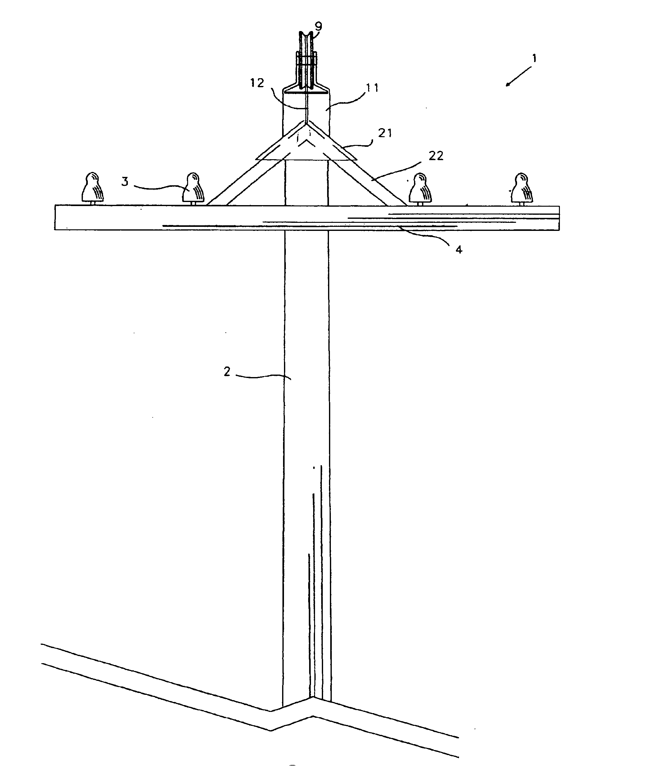
[0030] Referring now to the drawings, the attached figures illustrate a Utility Pole and Tower Safety and Protection Device 1.

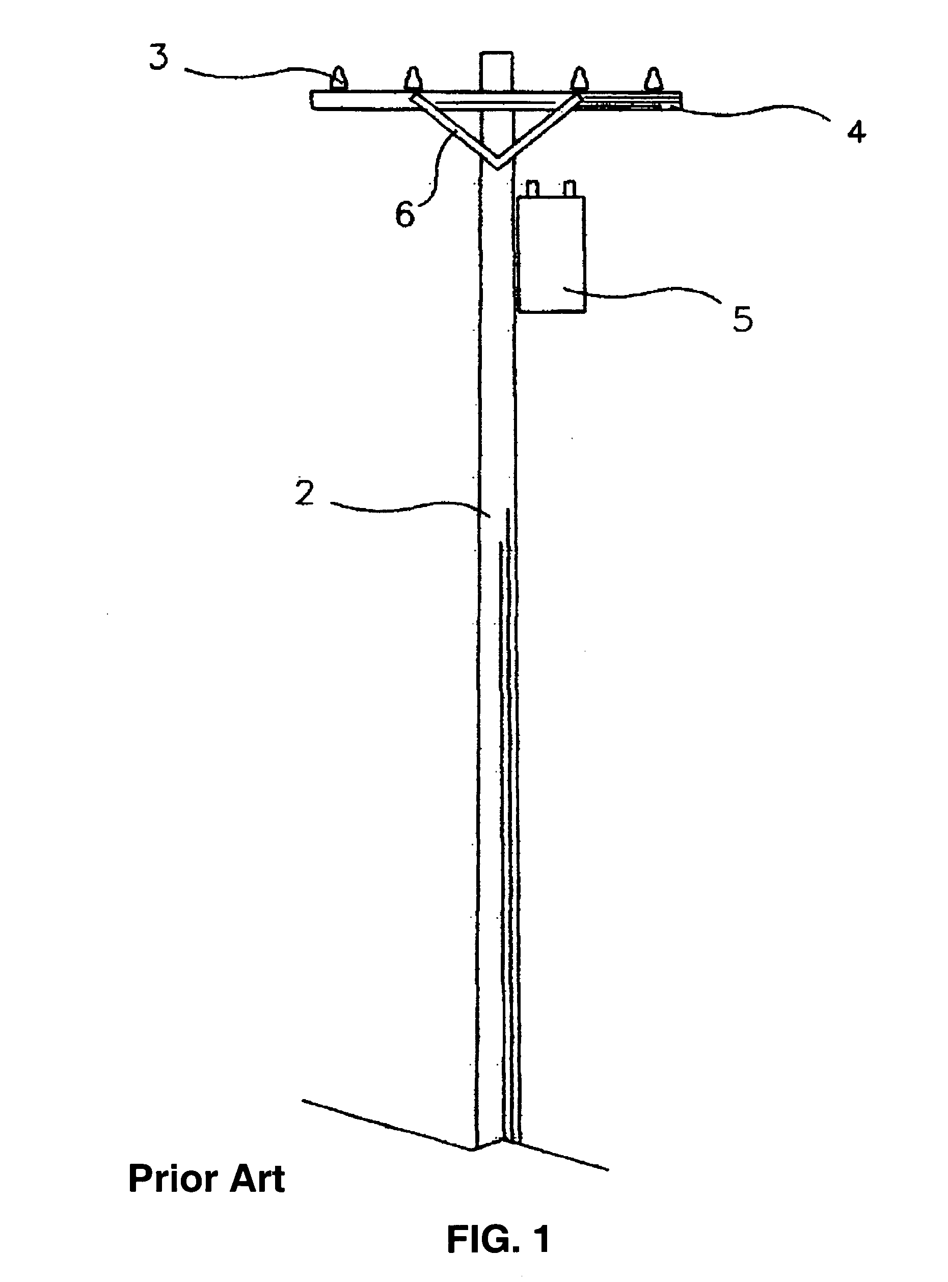
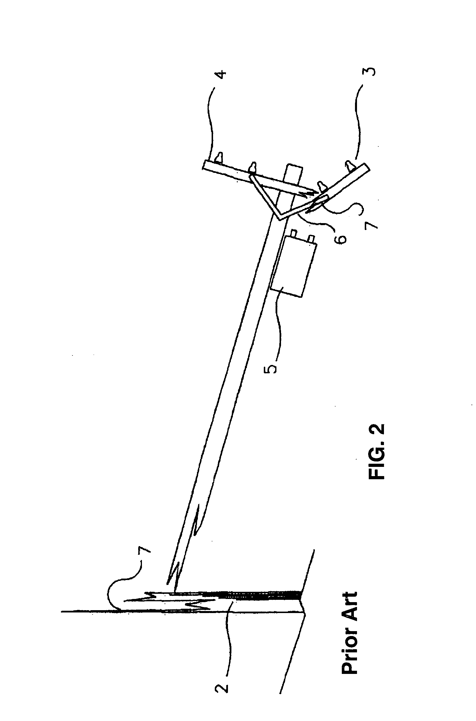
[0031]FIG. 1 and are provided to illustrate utility poles 2 of prior art. The pole 2 includes a cross arm 4, insulators 3, and a brace 6 affixed in typical position below the cross arm 4. A transformer 5 is illustrated in typical mounting position below the cross arm 4. The poles 2 may be wood or metal towers or any suitable structure that can support the device 1. FIG. 2 demonstrates devices of prior art in a broken state 7. As shown in FIG. 1, the fallen poles 2 and cross arms 4 are typically oriented in a position to cause damage 7 to the cross arms 4 as they fall.

[0032]FIG. 3 provides a clear view of a pulley or bearing 9 which channels a cable 12 about a mounting bracket 11. The mounting bracket 11 has a docking yoke 21. A docking brace 22, which provides attachment and stability to cross arm 4 engages the docking yoke 21. The cable 12 is attached to t...


PUM


Abstract

A Utility Pole and Tower Safety and Protection Device includes a utility pole with a crossbar to support utility conductors. The crossbar is attached to the pole with a release mechanism. A pressure transducer is attached to the release mechanism and automatically controls the release and descent of the crossbar at a predetermined load limit. A shear pin may also be used if a mechanical system is desired. An alarm system is attached to the pole and linked to a relay station announces when the system is activated. Power and continuity to the utility conductors is terminated when the system is activated, virtually eliminating the risks of a downed utility conductor. The device protects power and utility lines from breakage due to external forces, such as weather or trees. When the external force is removed, the device is reset by winching the crossbar into position and resetting the release mechanism.

Description

PRIORITY DATA [0001] This application is a claims priority from U.S. Patent Application Ser. No. 60 / 648,259 filed on Jan. 28, 2005, entitled “Utility Pole And Tower Safety And Protection Device” and is hereby incorporated by reference.FIELD OF THE INVENTION [0002] This invention relates generally to the field of utility poles. More specifically, it relates to such apparatus for utility poles and towers for protection against electrical shock with downed conductors, telephone lines, broken poles and towers as a result of adverse weather such as ice storms, strong winds and the like. Additionally, the new and novel device provides for much faster restoration of power and services while saving large amounts of money and resources. BACKGROUND OF THE INVENTION [0003] Prior Art utility pole and towers are permanently assembled with cross arms, conductors, insulators and the like. These assemblies are costly to purchase, assemble and maintain. Historically, thousands of miles of utility li...

Claims


Application Information

Patent Timeline
Patent Type & Authority Applications(United States)
IPC IPC(8): H02G3/32
CPCH02G7/02H02G7/18
Inventor BELL, DENNIS LEE
Owner MILLER MICHAEL L MR
Why Eureka
Try Eureka