Fiber optical system with Raman tilt control

Inactive Publication Date: 2006-08-03
ALCATEL LUCENT SAS
View PDF14 Cites 6 Cited by
  • Summary
  • Abstract
  • Description
  • Claims
  • Application Information

AI Technical Summary

Benefits of technology

[0021] In a further preferred variant, the number of channels of the optical signal is varied by reconfigurable add/drop multiplexing. The ability to add and drop waveleng

Problems solved by technology

It is difficult to maintain a flat, i.e. approximately constant, gain for all the spectrum of the amplified wavelength band when the number of channels is changed (especially when a fiber is cut and the number of channels decreases very quickly).
For ultra long haul systems with a large number of amplifiers Raman tilt

Method used


Image

  • Fiber optical system with Raman tilt control
  • Fiber optical system with Raman tilt control
  • Fiber optical system with Raman tilt control

Examples


Embodiment Construction

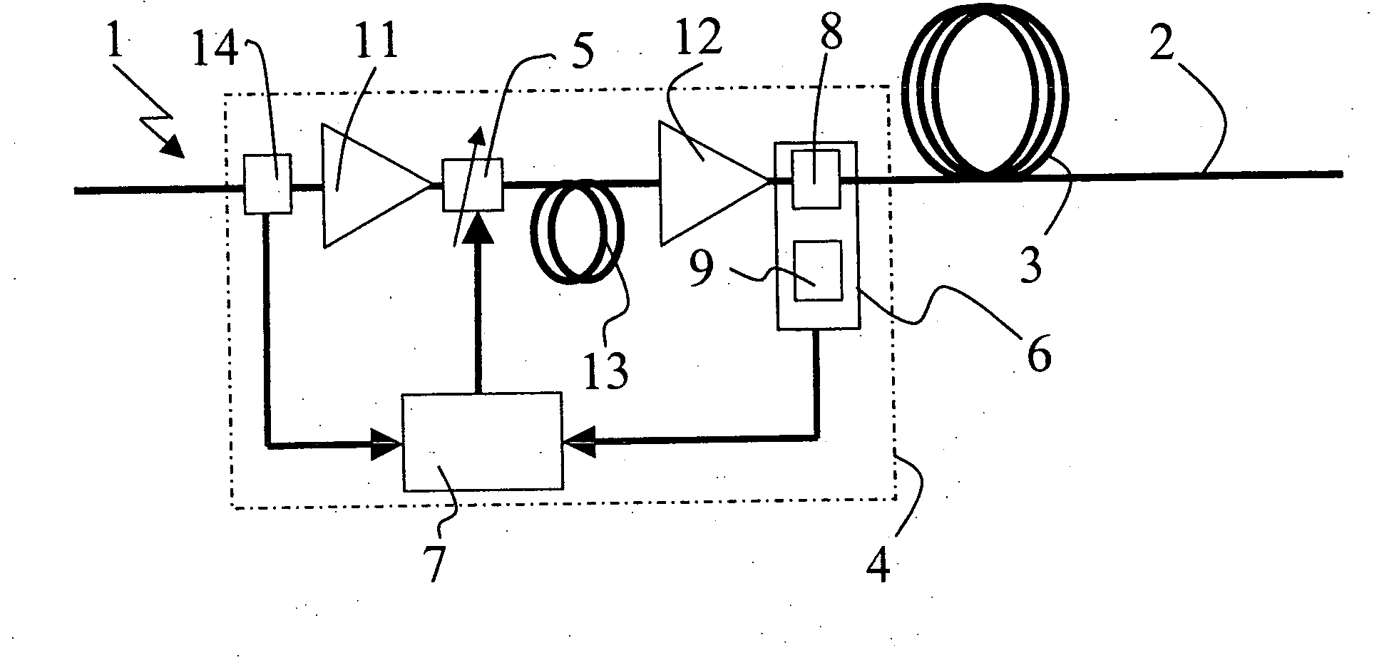
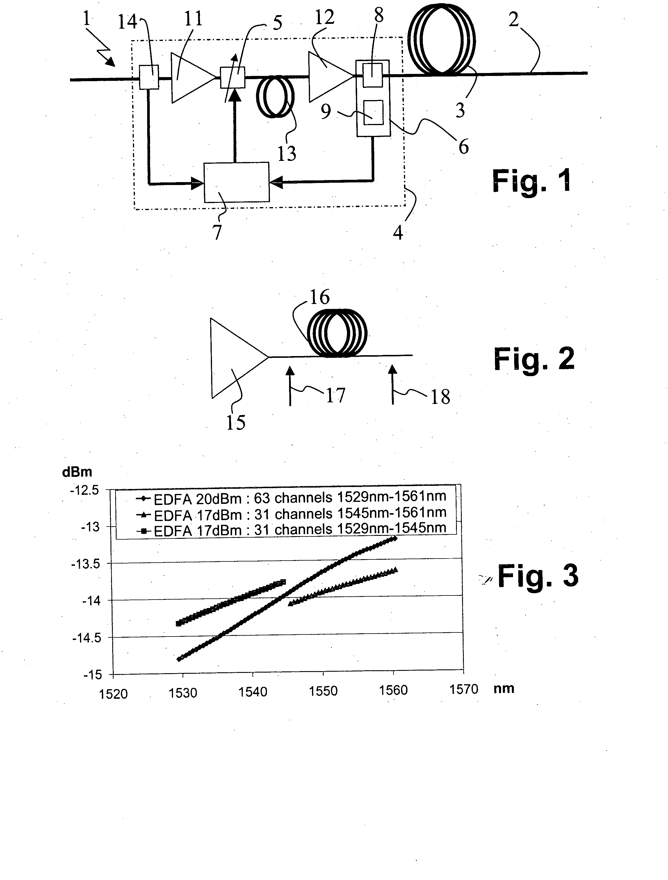
[0029]FIG. 1 shows a detail of a fiber optical system 1 with an optical fiber line 2 through which an optical signal is transmitted. The optical fiber line 2 is divided into a plurality of optical fiber spans 3, one of which is shown in FIG. 1. The optical fiber span 3 follows an optical amplifier 4. The whole fiber optical system 1 consists of a series of arrangements as shown in FIG. 1.

[0030] The optical amplifier 4 comprises a variable optical attenuator (VOA) 5 generating a gain tilt of the amplification of the optical signal, a Raman tilt determining device 6 for determining a Raman tilt induced in the fiber span 3 following the optical amplifier 4, and a dynamic controller 7 connected to the variable optical attenuator 5 and to the Raman tilt determining device 6. The dynamic controller 7 serves for adjusting the gain tilt of the optical amplifier 4 such that the Raman tilt induced in the following fiber span 3 is compensated for.

[0031] The Raman tilt determining device 6 co...


PUM


Abstract

A fiber optical system (1) for transmitting an optical signal comprises an optical fiber line (2) with a plurality of optical fiber spans (3) interconnected by a plurality of optical amplifiers (4). Each optical amplifier (4) comprises: At least one variable optical attenuator (5) generating a gain tilt of the amplification of the optical signal, a Raman tilt determining device (6) for determining a Raman tilt induced in the fiber span (3) following the optical amplifier (4), and a dynamic controller (7) connected to the variable optical attenuator (5) and to the Raman tilt determining device (6) adjusting the gain tilt such that the Raman tilt is compensated for.

Description

[0001] The invention is based on a priority application EP 05290218.6 which is hereby incorporated by reference. FIELD OF THE INVENTION [0002] The invention relates to a fiber optical system for transmitting an optical signal, comprising an optical fiber line with a plurality of optical fiber spans interconnected by a plurality of optical amplifiers. BACKGROUND OF THE INVENTION [0003] Stimulated Raman scattering (SRS) is one of the dominant fiber non-linear effects. SRS causes a transfer of energy from photons with high optical power to photons with low optical power. In dense wavelength division multiplexed (DWDM) systems SRS is responsible for a transfer of power from lower wavelength channels to higher wavelength channels, causing a Raman tilt in the per channel power so that lower wavelength channels have smaller per channel power than higher wavelength channels. [0004] In fiber optical systems, in particular ultra long haul (ULH) optical systems with multiple reconfigurable opt...

Claims


Application Information

Patent Timeline
IPC IPC(8): H01S3/00H04B10/291H04B10/296
CPCH04B10/2916H04B10/296
Inventor CHARLET, GABRIELSIMONNEAU, CHRISTIAN
Owner ALCATEL LUCENT SAS
Why Eureka
Try Eureka