Stator and electric motor having the same

Inactive Publication Date: 2006-08-24
SAMSUNG ELECTRO MECHANICS CO LTD
View PDF2 Cites 6 Cited by
  • Summary
  • Abstract
  • Description
  • Claims
  • Application Information

AI Technical Summary

Benefits of technology

[0016] The present invention has been made to solve the foregoing problems of the prior art and it is therefore an object of the present invention to provide a stator an

Problems solved by technology

If this connecting part of the coil bridges directly from a tooth to another, the winding procedure of the coil is hindered, causing disconnection, etc.
However, the above construction of the conventional stator core 10a requires additional installation of the synthetic resin ring 19 on the uppermost part of the core plates 14, with so many assembl

Method used


Image

  • Stator and electric motor having the same
  • Stator and electric motor having the same
  • Stator and electric motor having the same

Examples


Example

[0040] Preferred embodiments of the present invention will now be described in detail with reference to the accompanying drawings.

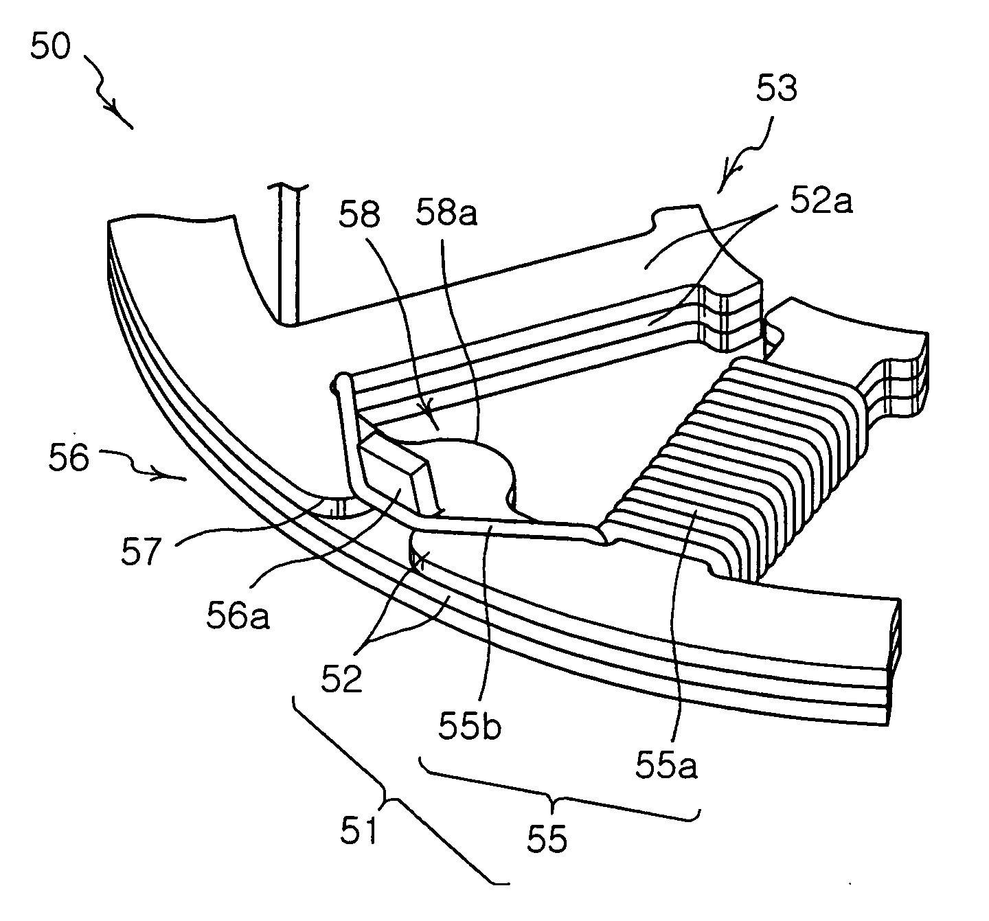
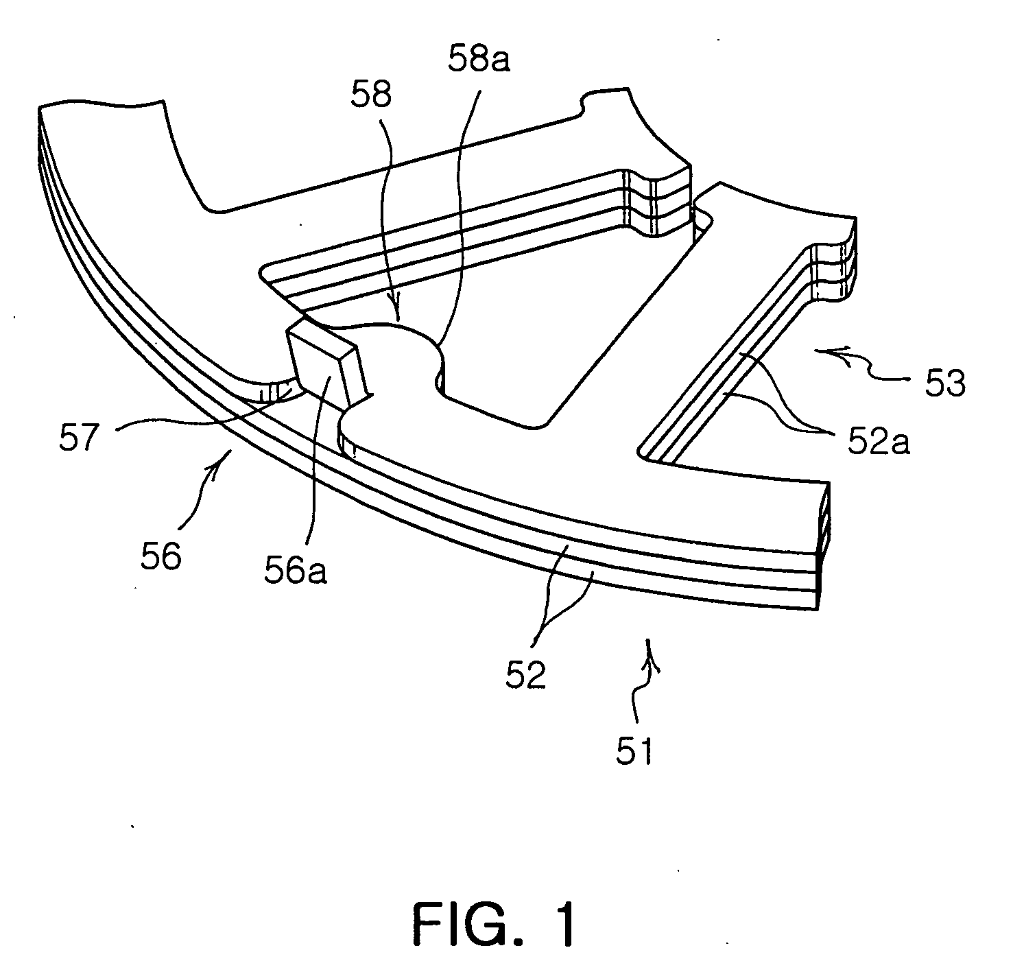
[0041]FIG. 1 is a detailed view of a core provided in a stator according to the present invention, and FIG. 2 is a detailed view of the stator according to the present invention.

[0042] As shown in FIGS. 1 and 2, the stator of the present invention 50 includes an annular core 51 and at least one coil 55 wound on the same.

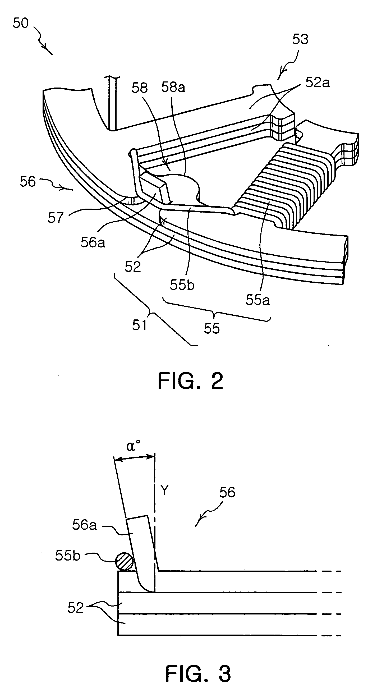
[0043] The core 51 is formed with a plurality of core plates 52, which are thin metal plates cut and processed in an annular shape, piled up in a thickness direction Y on one another in at least two layers.

[0044] In the inner side of each core plate constituting the core 51, a plurality of protrusion parts 52a, each extending in a predetermined length toward the inner circumference, are provided in a regular interval on the circumference of the core 51. With this configuration, a plurality of teeth 53 forming winding parts 55a with the...


PUM


Abstract

The present invention provides a stator including a core having a plurality of core plates piled on one another, and a plurality of teeth formed in a regular interval on the circumference of the core. The stator also has a plurality of protuberant parts bent upward from outside to inside on one of the plurality of core plates. The stator further has at least one coil having winding parts wound on the teeth of the core and connecting parts hitched on the protuberant parts. The present invention allows simpler bending process of the core, with fewer molds, thus reducing the manufacture cost and the manufacture time to enhance productivity.

Description

CLAIM OF PRIORITY [0001] This application claims the benefit of Korean Patent Application No. 2005-13988 filed on Feb. 21, 2005, in the Korean Intellectual Property Office, the disclosure of which is incorporated herein by reference. BACKGROUND OF THE INVENTION [0002] 1. Field of the Invention [0003] The present invention relates to a stator and an electric motor having the same, and more particularly, to a stator and an electric motor having the same in which the bending process of a core is simpler with a reduced number of molds for bending the core, reducing the manufacturing costs and time to increase productivity. [0004] 2. Description of the Related Art [0005] In general, an electric motor (hereinafter referred to as “motor”) is an apparatus for converting electric energy into mechanical energy. The motor can be categorized into many different kinds depending on the type of power, the method of activation, the type of rotor, and the type of external structure such as frame and...

Claims


Application Information

Patent Timeline
IPC IPC(8): H02K1/00H02K3/46
CPCH02K3/522H02K1/14H02K1/165H02K15/026H02K3/48
Inventor YANG, KYOUNG SOOHAN, MOON KYU
Owner SAMSUNG ELECTRO MECHANICS CO LTD
Why Eureka
Try Eureka