

Backlight button assemblage
- Summary
- Abstract
- Description
- Claims
- Application Information
AI Technical Summary
Benefits of technology
Problems solved by technology
Method used
Image

Examples
first embodiment
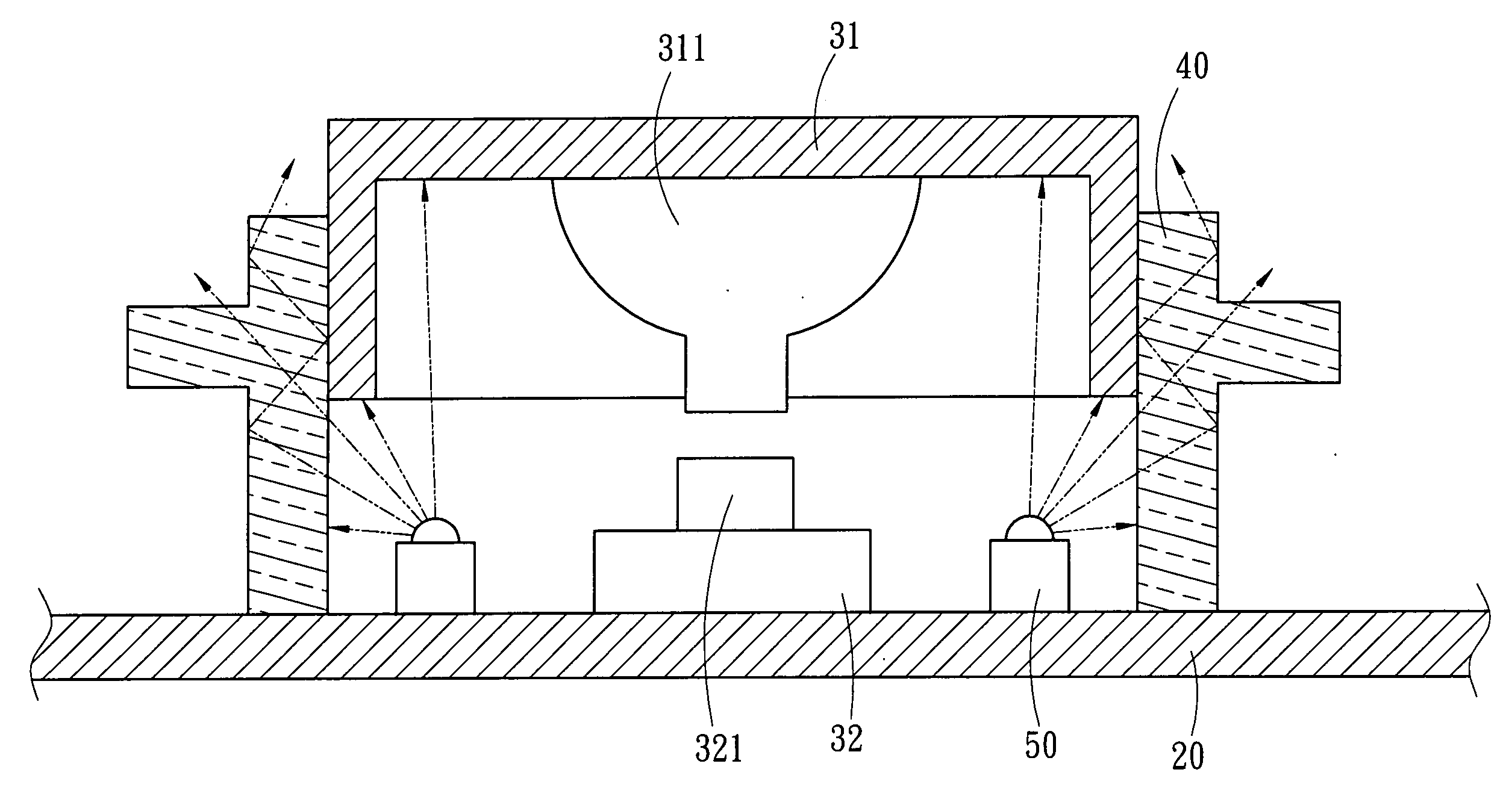
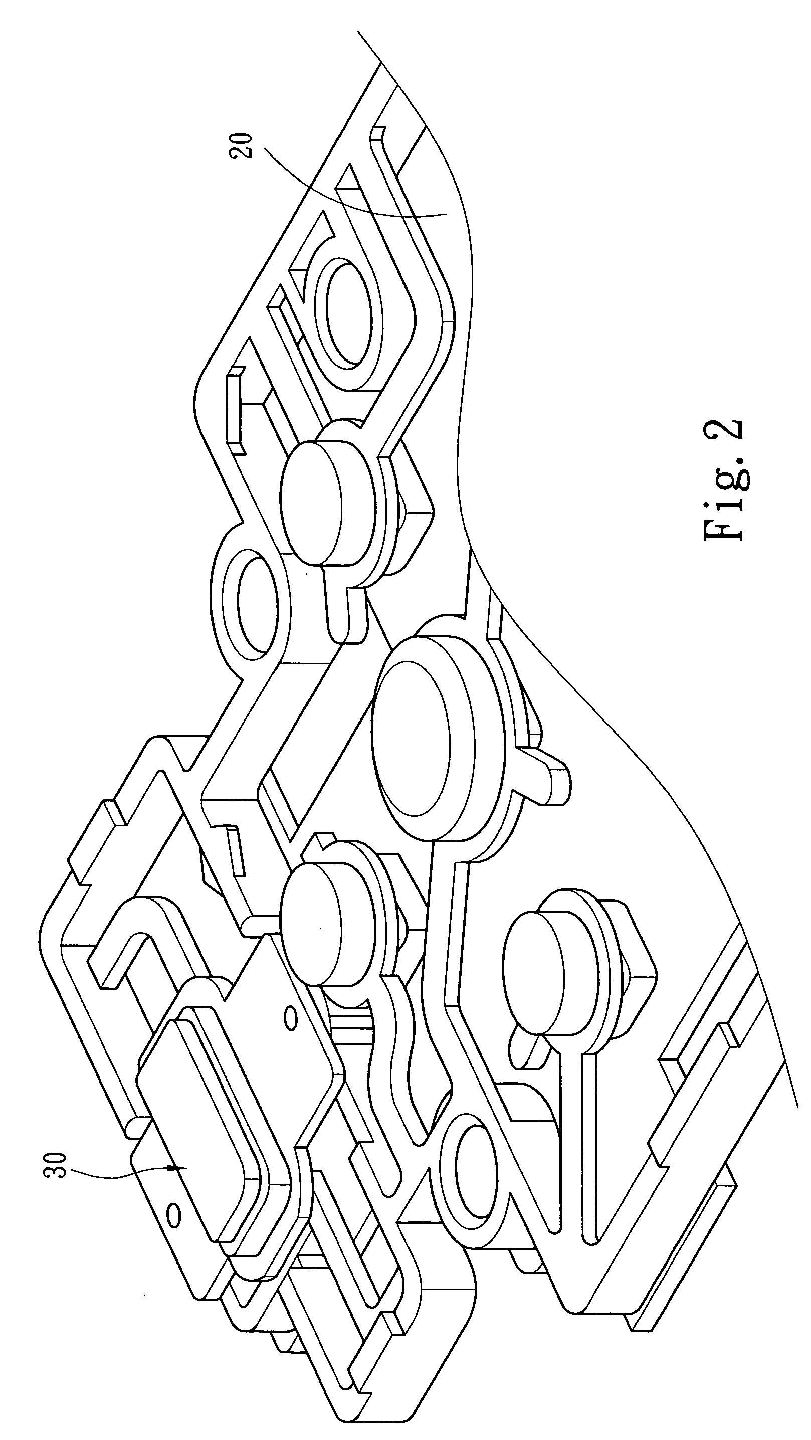
[0016] As shown in FIG. 2 and FIG. 3, according to the present invention, a backlight button assemblage 30 includes a button 31, a light-guiding element 40, and at least one light-emitting element 50.
[0017] The button 31 is opaque and disposed above a switch 32. A bottom of the button 31 usually has a protrusion 311, which is used to press a contact end 321 of the switch 32. In a normal state, the button 31 is supported by support elements, such as a spring (not shown), or directly supported by the contact end 321 of the switch 32.
[0018] The light-guiding element 40 is transparent. The shape of light-guiding element 40 matched a contour of the button 31 and is disposed along the perimeter of the button 31, The light-guiding element 40 can not interfere with a movement of the button 31. The light-guiding element 40 is annular, and is fixed to or stands on the surface of a printed circuit board (PCB) 20. The light-guiding element 40 guides a light and is made of a transparent materia...
second embodiment
[0021] Refer to FIG. 6, which discloses the backlight button assemblage in the present invention, a directional light-emitting element 50a is adopted. In this embodiment, the objectives of the present invention are achieved via a modification of the shape of the light-guiding element and the position of the light-emitting element 50a. In this embodiment, the light-guiding element 40a is a transparent structure and has a L-shaped section, which has at least one corner 41. Two ends of the L-shaped transparent structure are a light incident surface 42 and a light-emitting surface 43 respectively. The light-emitting surface 43 surrounds the perimeter of the button 31. The light incident surface 42 is near and perpendicular to a surface of the PCB 20. The light-emitting element 50a is disposed in front of the light incident surface 42, and the light-emitting direction (indicated by the arrow B in FIG. 6) is parallel to the surface of the PCB 20. The light-emitting direction of a light em...
PUM
 Abstract
Description
Claims
Application Information