Optical system and image protection apparatus

an optical system and image protection technology, applied in the field of optical systems, can solve the problems of affecting the brightness of the image, affecting the even illumination of the liquid crystal panel, and affecting the display effect, so as to improve the contrast characteristic and display, and not deteriorate the evenness of the image brightness

Inactive Publication Date: 2006-09-28
CANON KK
View PDF9 Cites 7 Cited by
  • Summary
  • Abstract
  • Description
  • Claims
  • Application Information

AI Technical Summary

Benefits of technology

[0009] An object of the present invention is to provide an optical system including an optical integrator and a light intensity distribution converter, the optical system being capable of improving of its contrast characteristic and displaying of images which have a brightness according to the brightness of the use environment, without deteriorating evenness of image's brightness.

Problems solved by technology

However, a problem occurs when the means for variably shielding the illumination luminous flux, which has been proposed in Japanese Patent Laid-Open No. 2004-151674, is simply used in the illumination optical system that controls separately in the two-dimensional axis directions the optical integrator and the light intensity distribution converting means for converting the light intensity distribution, which has been described in Japanese Patent Laid-Open No. 2004-245977 and No. 2004-271887.
Specifically, since the illumination optical system is a system that adopts different illumination light transmission methods in the two directions, there is a possibility that a balance of even illumination of liquid crystal panels may disrupt and the evenness of the displayed image may be not maintained.

Method used


Image

  • Optical system and image protection apparatus
  • Optical system and image protection apparatus
  • Optical system and image protection apparatus

Examples


embodiment 1

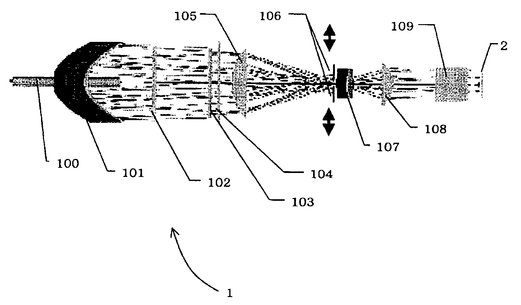
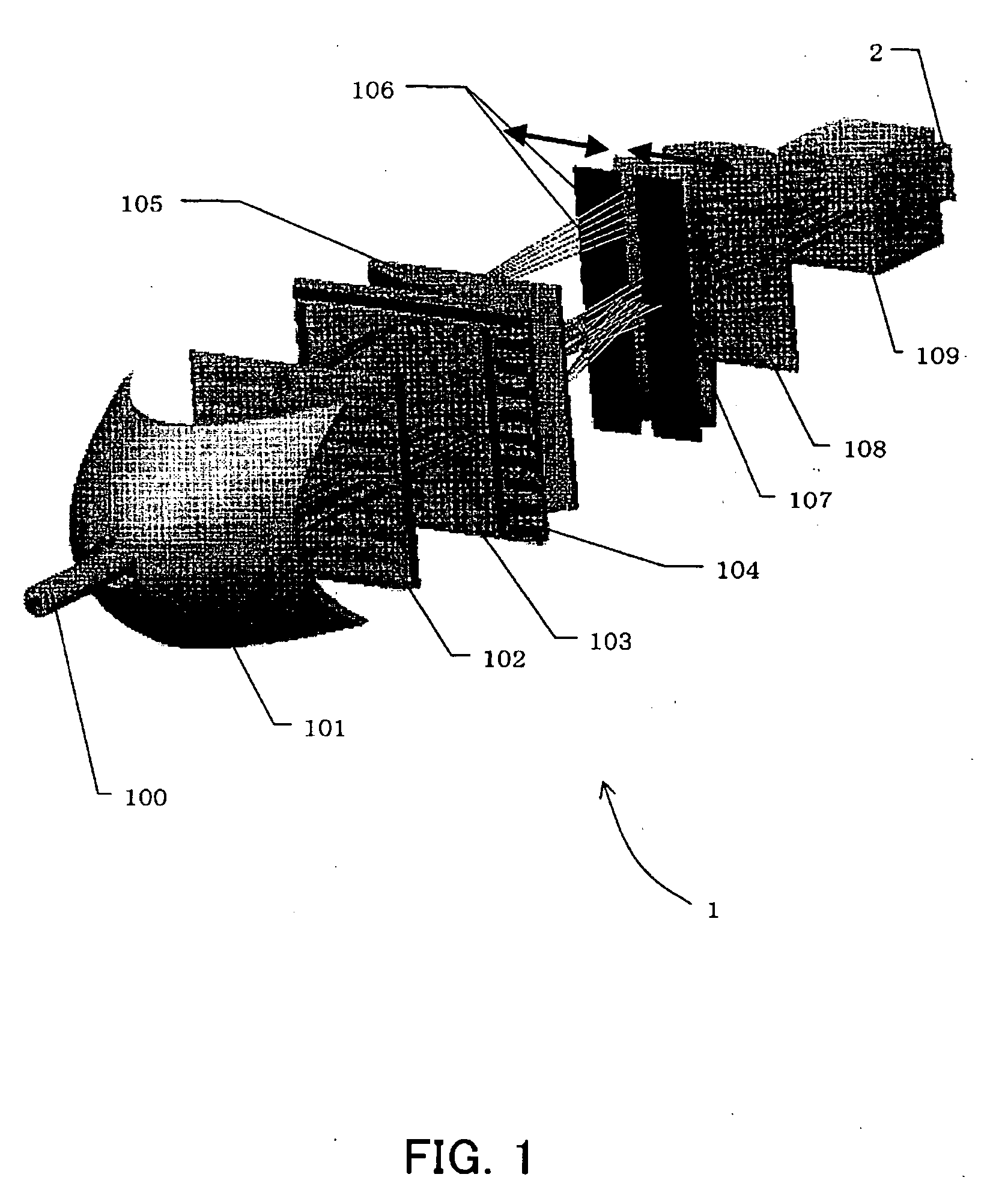
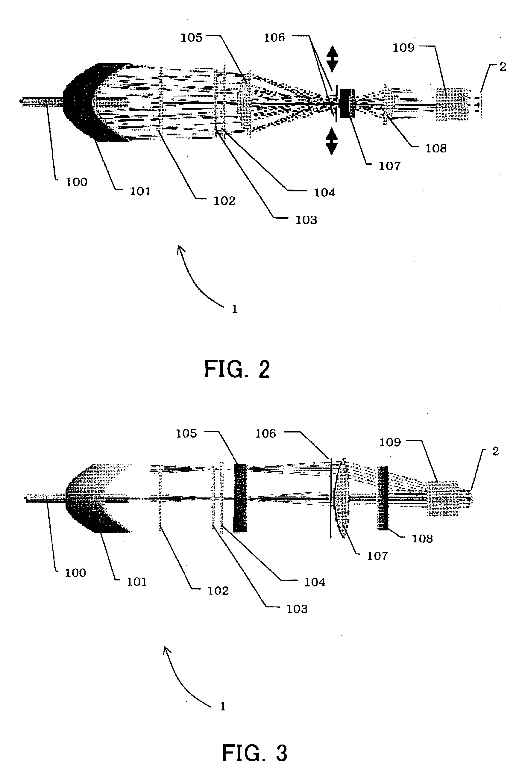
[0022] FIGS. 1 to 3 show the structure of an illumination optical system that is Embodiment 1 of the present invention. FIG. 1 is a perspective view showing the main structure of the illumination optical system, FIG. 2 is a top sectional view thereof. FIG. 3 is a side sectional view of the illumination optical system.

[0023] In these figures, 1 denotes the illumination optical system. 100 denotes a discharge gas excitation light-emitting lamp as a light source, such as a super high pressure mercury lamp, a metal haloid lamp, or a xenon lamp. The discharge gas excitation light-emitting lamp hereinafter is referred to simply as a light source lamp. A luminous flux emitted from the light source lamp 100 is parallelized by being reflected by a parabolic reflecting mirror 101, and the luminous flux thereby becomes a substantially parallel visible light beam.

[0024] However, the actual light source has a light emission distribution with a finite size (or the light emission area of the lig...

embodiment 2

[0059]FIG. 7 shows an embodiment of a liquid crystal projector (image projection apparatus) using the illumination optical system 1 of Embodiment 1. FIG. 7 shows a cross-section of the entire optical system of the projector. In the rectangular line in this figure, the right side area of the dashed line shows the top view of the illumination optical system 1, and the left side area of the dashed line shows the side view thereof.

[0060]3 denotes a controller which controls the whole operation of the projector and includes a driver for driving liquid crystal panels 2R, 2G and 2B. The driver converts video input signals (or image signals) from an image supplying apparatus 200, such as a personal computer, DVD player and television tuner, into liquid crystal drive signals for each color, and outputs the drive signals to the liquid crystal panel 2R for red, the liquid crystal panel 2G for green and the liquid crystal panel 2B for blue. Thereby, an original image is formed on each liquid c...


PUM


Abstract

An optical system is disclosed which is capable of improving of its contrast characteristic and displaying of images which have a brightness according to the brightness of the use environment. The optical system comprises an optical integrator which divides and recombines the illumination luminous flux in a first axis direction and a light intensity distribution converter which converts the light intensity distribution of the illumination luminous flux in a second axis direction. The optical system further comprises a luminous flux limiting unit which has an aperture. The size of the aperture is changeable in the second axis direction and unchangeable in the first axis direction.

Description

FIELD OF THE INVENTION [0001] The present invention relates to an optical system used in an image projection apparatus such as a projector, specifically to an optical system which illuminates an image-forming element such as a liquid crystal display element using light from a light source, and enlarges and projects an original image formed on the image-forming element onto a screen or the like. BACKGROUND OF THE INVENTION [0002] In projectors which use an image-forming element such as a liquid crystal panel, it is important to use light from a light source efficiently, reduce unevenness of illuminance on a screen, and display images having a high contrast. Many methods to improve them have been proposed in the past. [0003] For example, an optical integrator has been known which is constituted by two lens array, each having lens cells arranged two-dimensionally. In this optical integrator, a first lens array divides a luminous flux from a light source into a plurality of luminous flu...

Claims


Application Information

Patent Timeline
Patent Type & Authority Applications(United States)
IPC IPC(8): G02B26/08
CPCG02B5/005G02B27/283G03B21/208G02B27/00G02B27/18
Inventor KOIDE, JUN
Owner CANON KK
Why Eureka
Try Eureka