Patient interface with adjustable cushion
- Summary
- Abstract
- Description
- Claims
- Application Information
AI Technical Summary
Benefits of technology
Problems solved by technology
Method used
Image

Examples
first embodiment
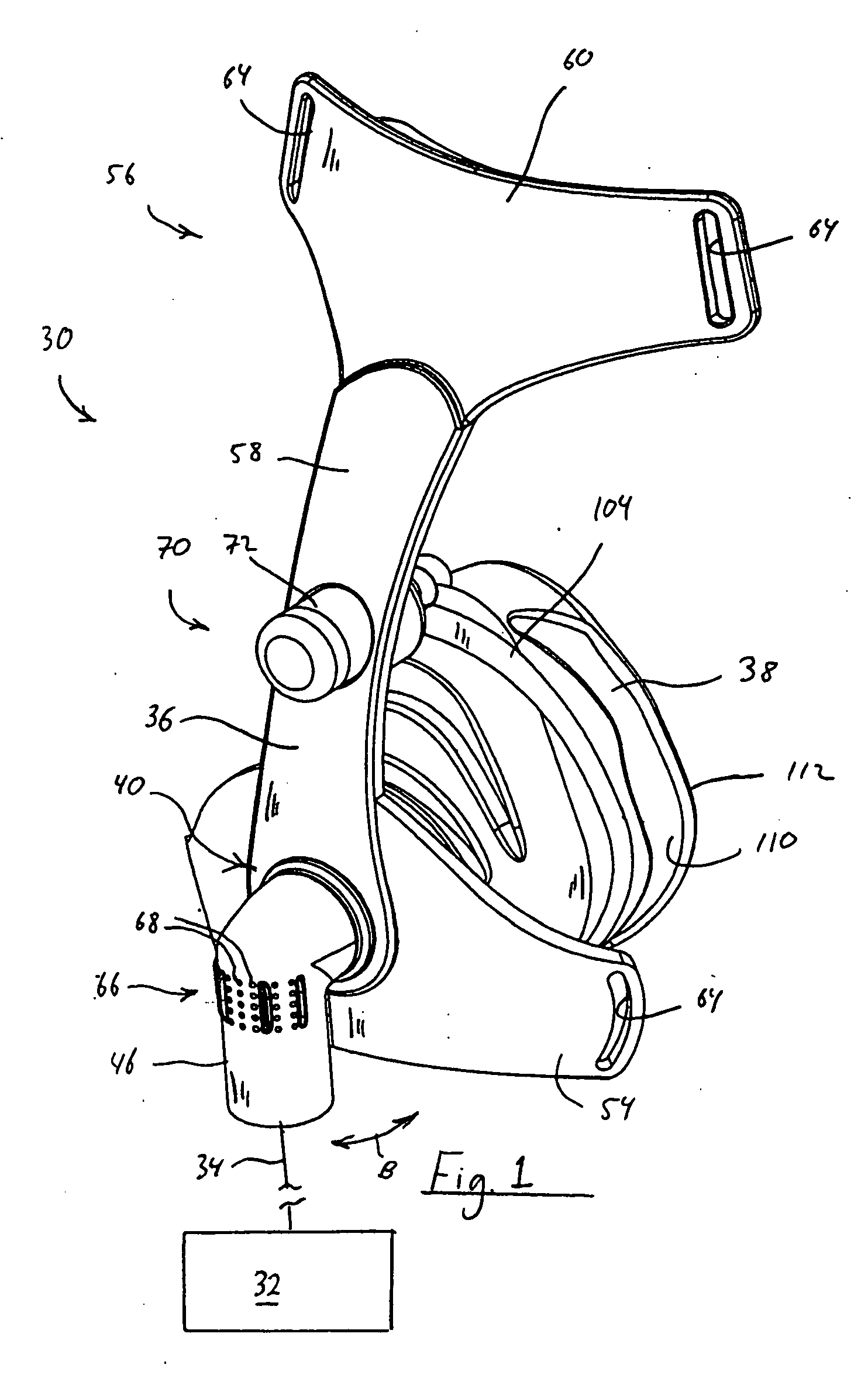
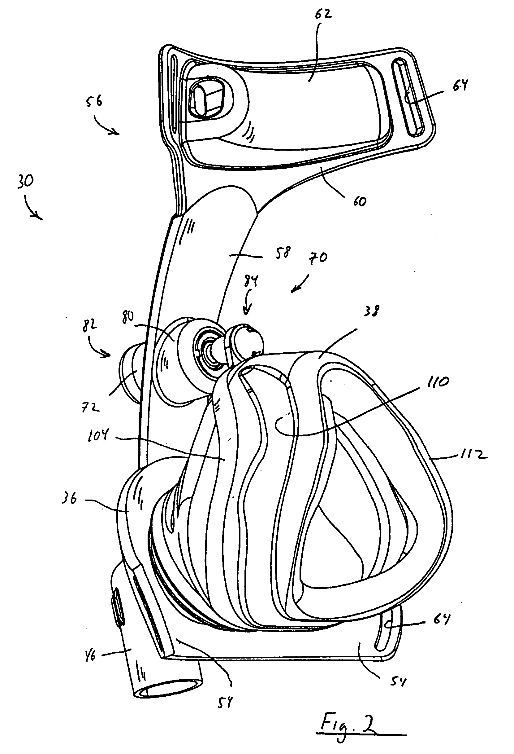
[0049]FIGS. 1-6 illustrate a patient interface 30 according to the principles of the present invention. Patient interface 30 is shown schematically connected to a pressure / flow generating system 32 via a patient circuit 34, which communicates gas from the pressure support system to the patient interface. Pressure / flow generating system 32 is any conventional ventilator or pressure support system. Patient circuit 34 is typically a flexible hose or tube that communicates an output of the pressure / flow generating system with the patient interface. It is to be understood that other accessories used in pressure / flow generating systems, such as a humidifier, pressure sensor, flow sensor, temperature sensor, humidity sensor, bacteria filter, etc. can be used in conjunction with the patient interface of the present invention.
[0050] Examples of pressure support systems include, but are not limited to: a ventilator, continuous positive airway pressure (CPAP) device, or a variable pressure dev...
third embodiment
[0076]FIGS. 12-14 illustrate an example of a third embodiment for a patient interface 200 that includes multiple contact points between faceplate 202 and a seal member 204 to provide greater control over the position of the patient contacting portion of the seal member relative to the faceplate than in the previous embodiments. In this embodiment, seal member 204 comprises a cushion 206, a flap 208, and a seal mount member 210. In this particular embodiment, flap 208 includes an attachment ring 212 that snaps onto an outer edge portion 214 of the seal mount member capturing the cushion between the seal mount member and the flap. In the assembled configuration, the seal member.
[0077] The seal member is coupled to the faceplate by engaging the seal mount member with the faceplate at three attachment points. Two of the attachment points are at the lower left and right sides of the seal mount member, and the third is the attachment between the seal mount member and the faceplate provide...
fourth embodiment
[0083]FIGS. 15-17 illustrate a patient interface 300 according to the principles of the present invention. Patient interface 300 includes a faceplate 302 and a seal member 304 coupled to the faceplate. The seal member includes a cushion 306, a collar 308, and a seal mount member 310 to which the cushion and collar are mounted or otherwise attached. The seal mount member is coupled to the faceplate via and adjustment mechanism 316. The seal member is also coupled to the faceplate via collar 308, which communicates the interior of the seal member with coupling member 46.
[0084] As best illustrated in FIG. 17, collar 308 includes a first end portion 311 that attaches to faceplate 302, coupling member 46, the patient circuit, or any combination thereof. A second end portion 312 attaches to seal mount member 310. Collar 308 is formed from a flexible or material or is structured so as to be flexible so that the position of the seal member can be adjusted relative to the faceplate while all...
PUM
 Abstract
Description
Claims
Application Information