Pressing iron having an improved cord guide device

Inactive Publication Date: 2007-03-22
SEB SA
View PDF7 Cites 1 Cited by
  • Summary
  • Abstract
  • Description
  • Claims
  • Application Information

AI Technical Summary

Benefits of technology

[0003] The present invention overcomes these drawbacks by providing a pressing iron having a cord guide device that can guide a relatively long length o

Problems solved by technology

However, such a maintenance rod is not useable with an iron whose power cord is disposed at a lower position, close to the center of the heel of the iron, and not near the top.
In addition, such a maintenan

Method used


Image

  • Pressing iron having an improved cord guide device
  • Pressing iron having an improved cord guide device
  • Pressing iron having an improved cord guide device

Examples


Embodiment Construction

[0026] In the present description and illustrations, only the elements needed for an understanding of the invention will be described and shown. In order to facilitate an understanding of the drawings, the same elements are given the same reference numerals from one figure to another.

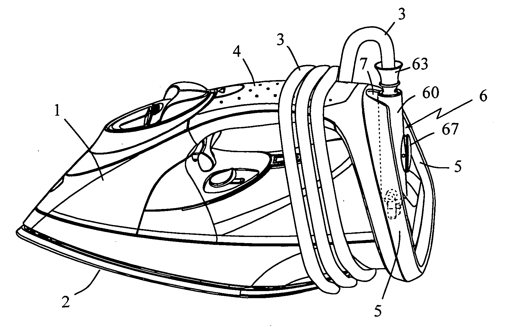
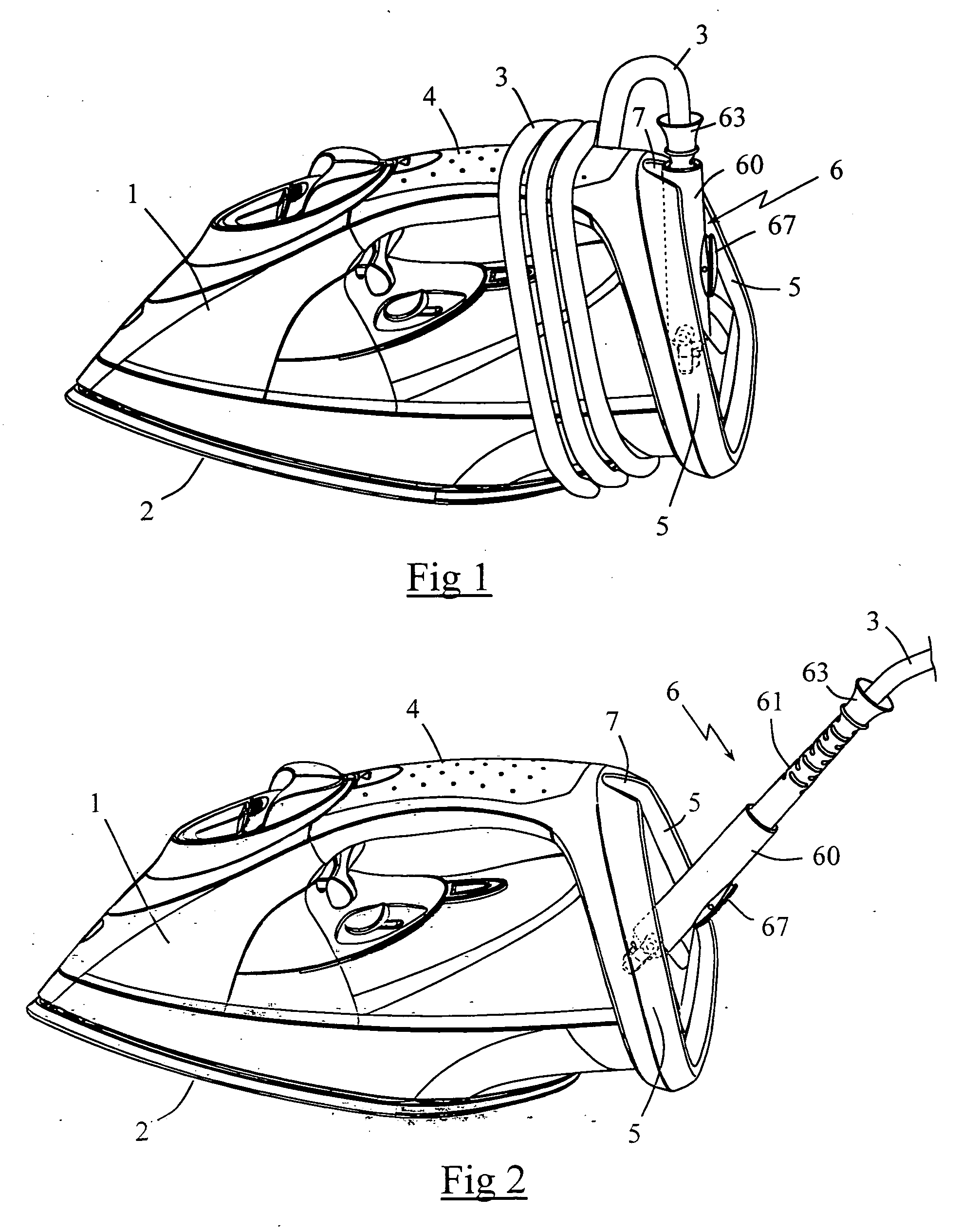
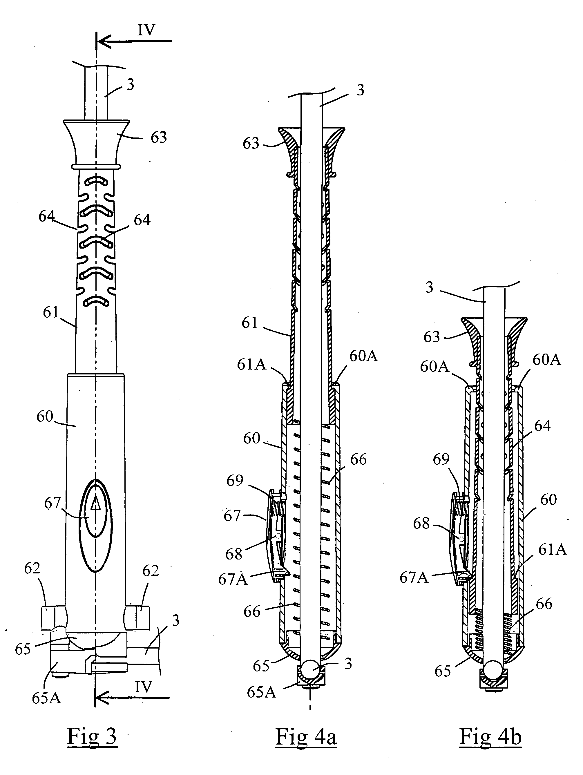
[0027]FIGS. 1 and 2 show a pressing iron having a plastic housing 1 that carries a soleplate 2 connected to the bottom of housing 1. Soleplate 2 is heated, in a conventional manner, by an electric resistance that receives electric power through a power cord 3. One end of cord 3 is provided with an electric plug (not shown) for connecting the iron to an electric outlet.

[0028] As shown in FIG. 1, housing 1 includes a handle 4 that is connected to the rear end of the iron by two arms 5 extending in a diverging manner from handle 4 to the body of the iron so that the resulting structure has a substantially triangular shape. Arms 5 delimit, and enclose, an open space at the rear of the iron, where the iron...


PUM


Abstract

A pressing iron composed of a case provided with an opening and a power cord that extends from the opening, and a cord guide device mounted to the case and disposed in the opening for reinforcing the cord in a region adjacent to the case in order to limit flexure of the cord. The cord guide device includes a body enveloping a portion of the cord and a mobile guide member for permitting the extent of the cord that is reinforced by the cord guide device to be varied. The mobile guide member is supported by the body and is adapted to occupy a folded up position in which the mobile guide member is substantially integrated into the body and a deployed position in which the mobile guide member projects outside of the body.

Description

BACKGROUND OF THE INVENTION [0001] The present invention relates to a pressing iron having a housing, or case, provided with an opening into which a flexible power cord extends and receiving a cord guide device to limit flexure, or bending, of the cord at the outlet of the housing. [0002] The patent document DE 93 06 930U discloses a pressing iron having a power cord that is reinforced locally by a flexible cord guide device that surrounds the cord adjacent to the housing of the iron. The iron also has a maintenance shank, or rod, pivotally mounted on the heel of the iron and adapted to occupy a deployed position in which the free end of the rod comes to support the cord at a point relatively distant from the cord outlet in order to displace the cord and a folded up position in which the rod is folded up against the heel of the iron. With such a solution, the maintenance rod in the deployed position presents the advantage of extending the cord in order to prevent it from rubbing aga...

Claims


Application Information

Patent Timeline
IPC IPC(8): D06F79/02
CPCD06F75/28
Inventor GIOVALLE, CHRISTIANMAUDHUIT, SYLVAINDJERORO, AMAR
Owner SEB SA
Why Eureka
Try Eureka