Turbo compressor and centrifugal chiller comprising same

Pending Publication Date: 2021-01-14
MITSUBISHI HEAVY IND THERMAL SYST
View PDF0 Cites 2 Cited by
  • Summary
  • Abstract
  • Description
  • Claims
  • Application Information

AI Technical Summary

Benefits of technology

[0018]In the turbo compressor and the centrifugal chiller including the turbo compressor according to the present disclosure, the length of the shaft in the axial

Problems solved by technology

In this case, there is a concern over a complicated structure caused by providing a l

Method used


Image

  • Turbo compressor and centrifugal chiller comprising same
  • Turbo compressor and centrifugal chiller comprising same
  • Turbo compressor and centrifugal chiller comprising same

Examples


Embodiment Construction

[0027]Hereinafter, a turbo compressor according to an embodiment of the present disclosure will be described.

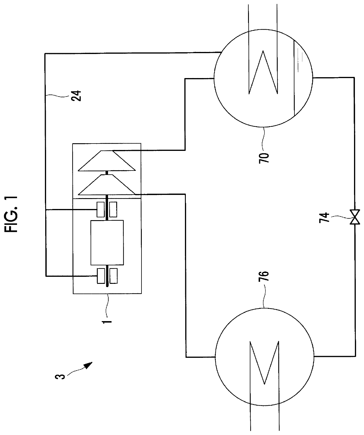
[0028]As shown in FIG. 1, a turbo compressor 1 is one of devices configuring a refrigerant circuit 3 of a centrifugal chiller. The refrigerant circuit 3 includes the turbo compressor 1, a condenser 70 that condenses a refrigerant compressed by the turbo compressor 1, an expansion valve 74 that expands the refrigerant condensed by the condenser 70, and an evaporator 76 that evaporates the refrigerant expanded by the expansion valve 74. The turbo compressor 1 is a turbo compressor that compresses a low-pressure gas refrigerant evaporated by the evaporator 76 to make into a high-temperature and high-pressure gas refrigerant.

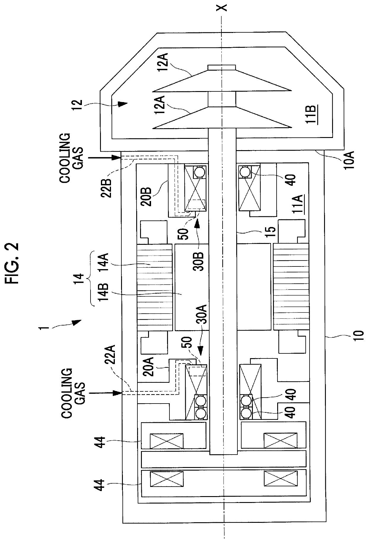
[0029]As illustrated in FIG. 2, the turbo compressor 1 is configured to include a casing 10 that forms an outer shell thereof, a compression portion 12 that has a plurality of impellers 12A, an electric motor 14, a shaft 15, and radial magnetic bearings (magn...


PUM


Abstract

Provided are a turbo compressor and a centrifugal chiller comprising the same with which the length of a shaft in an axial direction can be shortened, rotational shake accompanying rotation of the shaft is suppressed, and a device can be made small. A turbo compressor comprising: a compressor part which compresses refrigerant; a shaft (15) which drives the compressor part around an axis of rotation X; a magnetic bearing (30A) which has provided thereto an iron core part (32) comprising a plurality of teeth parts (34) formed at equiangular intervals around the axis of rotation X, and, a plurality of coils (36) respectively wound around the plurality of teeth parts (34), and said magnetic bearing (30A) allows the shaft (15) to pass through and supports said shaft (15) without contacting the same; an auxiliary bearing which allows the shaft (15) to pass through; and a displacement sensor (50) which detects displacement of the shaft (15), wherein the displacement sensor (50) is provided between neighboring coils (36).

Description

TECHNICAL FIELD[0001]The present disclosure relates to a turbo compressor and a centrifugal chiller including the turbo compressor.BACKGROUND ART[0002]In order to rotatably support a shaft that rotationally drives a compression mechanism, a contact-type bearing such as a rolling bearing is adopted in some cases in a turbo compressor. In this case, there is a concern over a complicated structure caused by providing a lubricant system of a bearing and a mechanical loss caused by friction of the bearing.[0003]For this reason, in order to omit the lubricant system and reduce the mechanical loss, a magnetic bearing that is a non-contact type bearing is adopted in some cases instead of the rolling bearing.[0004]As a structure of a fluid machine using the magnetic bearing, for example, there is a structure disclosed in FIG. 3 of PTL 1. In this structure, an auxiliary bearing and a displacement sensor are provided on both sides of the magnetic bearing along an axial direction of a shaft.CIT...

Claims


Application Information

Patent Timeline
IPC IPC(8): F25B1/053F04D29/058F25B9/06
CPCF25B1/053F25B9/06F04D29/058F04D29/059F25B49/022F04D17/122F04D29/5806F04D25/06
Inventor HASEGAWA, YASUSHIUEDA, KENJIOMURA, SHINTARO
Owner MITSUBISHI HEAVY IND THERMAL SYST
Why Eureka
Try Eureka