Fluid transportation machine

A fluid conveying and mechanical technology, used in mechanical equipment, liquid fuel engines, components of pumping devices for elastic fluids, etc., can solve problems such as impeller damage and cavitation, and achieve small, compact and high output. Effect

Inactive Publication Date: 2007-01-03
EBARA CORP
View PDF0 Cites 2 Cited by
  • Summary
  • Abstract
  • Description
  • Claims
  • Application Information

AI Technical Summary

Problems solved by technology

However, since the high-speed rotation of the pump causes cavitation and damages the impeller, there is a limit to increasing the rotation speed.

Method used


Image

  • Fluid transportation machine
  • Fluid transportation machine
  • Fluid transportation machine

Examples


Embodiment Construction

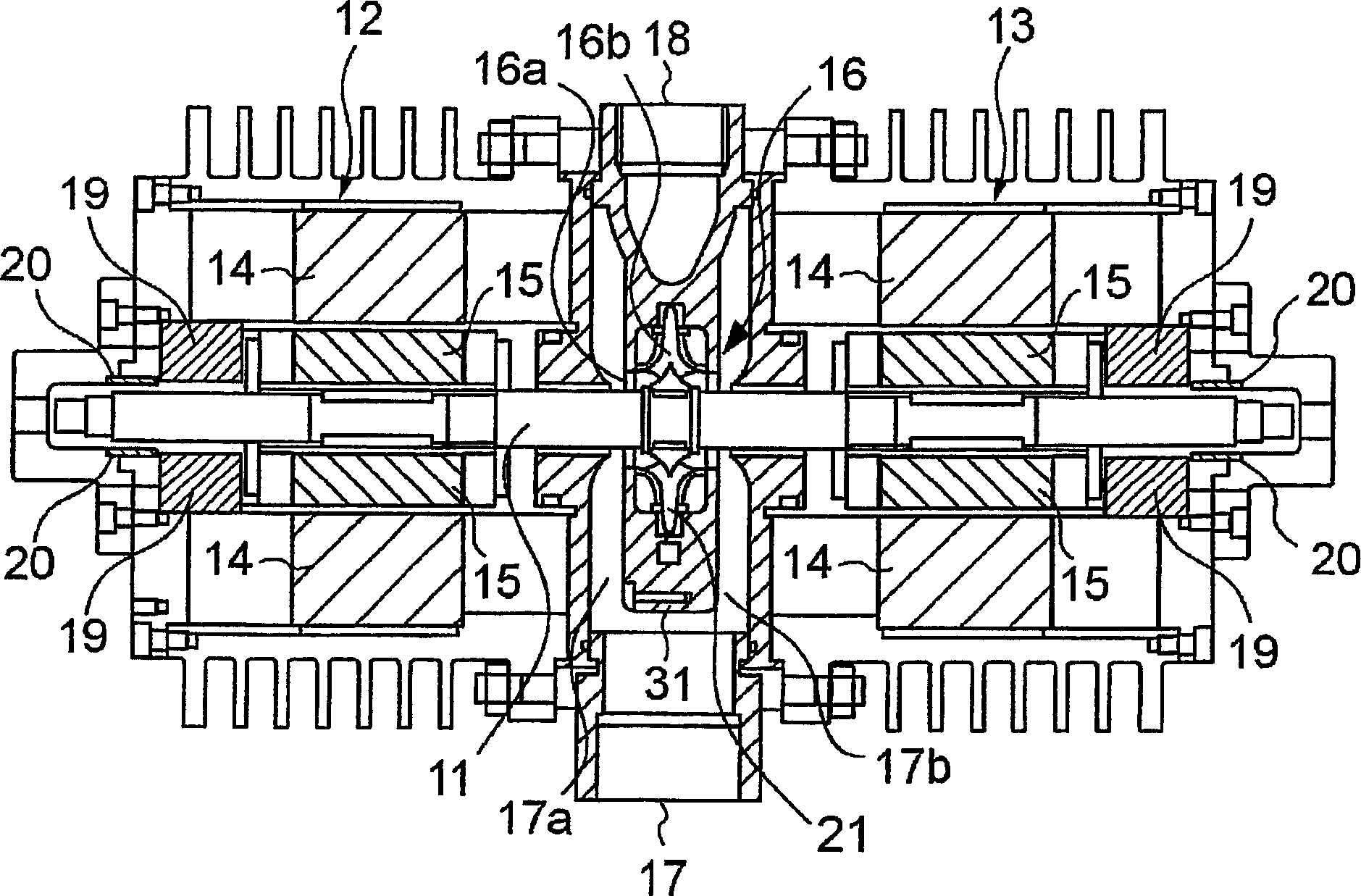
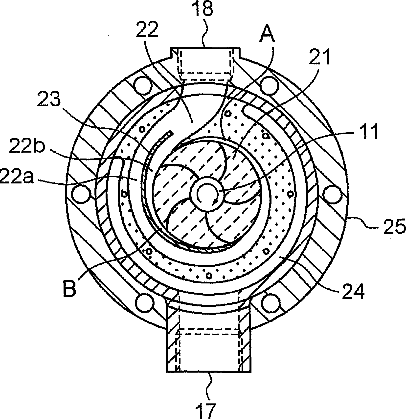
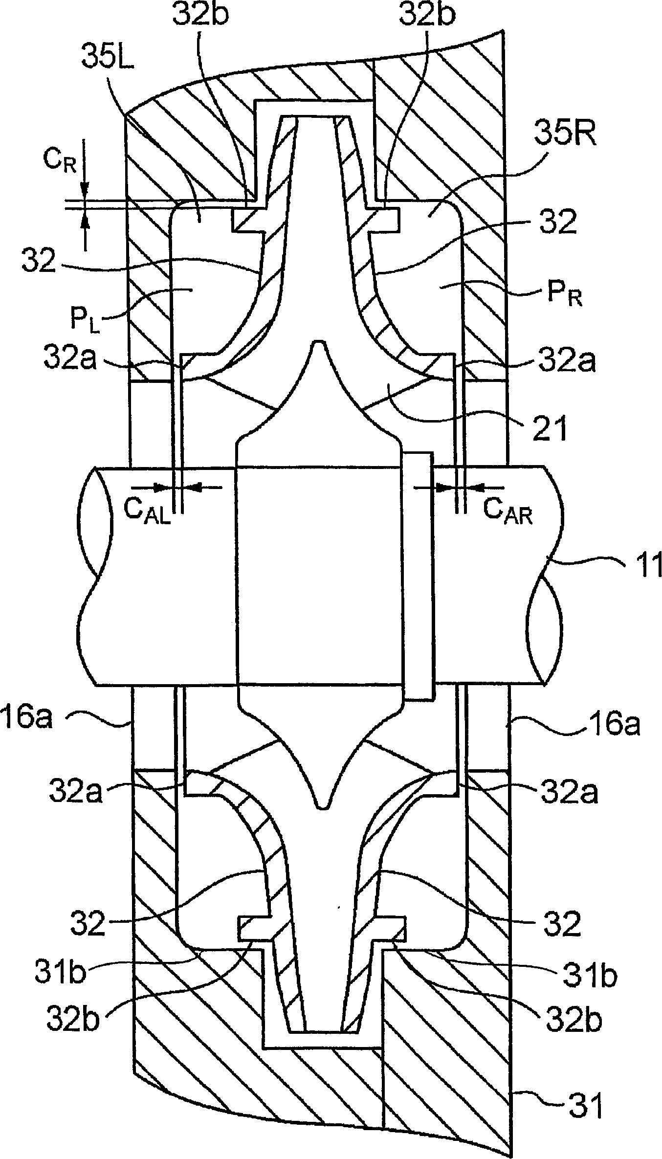
[0018] Refer below Figure 1 to Figure 4 A fluid transport machine according to an embodiment of the present invention will be described. In addition, in Figure 1 to Figure 4 In , components or elements having the same function are given the same reference numerals and repeated descriptions thereof are omitted.

[0019] figure 1 A double-suction pump (fluid transport machine) according to one embodiment of the present invention is shown. The fluid transfer machine includes a double-suction pump 16 at the center. The rotary shaft 11 of the pump 16 is rotationally driven by the magnetic levitation motors 12, 13 arranged on both sides of the pump 16, and is non-contact supported by the magnetic levitation motors 12, 13 which are radial magnetic bearings. Displacement sensors 19 are arranged on both sides of the magnetic levitation motors 12 and 13, and the magnetic levitation motors are controlled by a controller (not shown) according to the measured displacement of the rota...


PUM


Abstract

A fluid transportation machine has a rotating shaft (11), a double suction-type pump (16), and magnetic levitation motors (12, 13) having functions as radial magnetic bearings for supporting the rotating shaft (11) without contact and as motors for rotatingly driving the rotating shaft (11). The double suction-type pump (16) has a double suction-type blade wheel (21) attached to the rotating shaft (11), a pump casing (31) provided so as to surround the blade wheel (21), and a pressure balance mechanism for axially positioning the rotating shaft (11). The pump (16) is positioned at substantially the center of the rotating shaft (11), and the two magnetic levitation motors (12, 13) are arranged on both sides of the pump (16).

Description

technical field [0001] The present invention relates to a fluid conveying machine, in particular to a pump and other flow machines suitable for high-speed operation. Background technique [0002] In a common motor, the magnetic flux distribution in the gap between the stator and the rotor is rotationally symmetrical, and in principle no magnetic buoyancy force in the radial direction is generated. In contrast, the magnetic levitation motor can generate force in the radial direction by arranging the distribution of magnetic fluxes superimposed by the two rotating magnetic fields between the rotor and the stator to be biased. That is, there is known a magnetic levitation motor that forms two rotating magnetic fields with a difference in the number of poles of two in the stator, and applies a static magnetic force in the radial direction to the rotor by superimposing the two rotating magnetic fields with the different number of poles, and also provides a rotational driving forc...

Claims


Application Information

Patent Timeline
Patent Type & Authority Applications(China)
IPC IPC(8): F04D13/02F04D29/04F04D29/00F04D1/00F04D13/06F04D29/046F04D29/048F04D29/22F04D29/44
CPCF04D29/048F04D1/006
Inventor 佐藤忠森敏加藤弘之
Owner EBARA CORP
Why Eureka
Try Eureka