Optical projection apparatus

Inactive Publication Date: 2007-03-29
YOUNG OPTICS
View PDF8 Cites 8 Cited by
  • Summary
  • Abstract
  • Description
  • Claims
  • Application Information

AI Technical Summary

Benefits of technology

[0010] According to the foregoing description, the invention is to provide an optical projection apparatus, in which the position of t

Problems solved by technology

Although the elements of the optical projection apparatus 100 become miniaturized, the accuracy for assembling the optical projection apparatus 100 is not as good as expected.
Therefore, the image quality is degraded.
However, it is unavoidable that stray

Method used


Image

  • Optical projection apparatus
  • Optical projection apparatus
  • Optical projection apparatus

Examples


Embodiment Construction

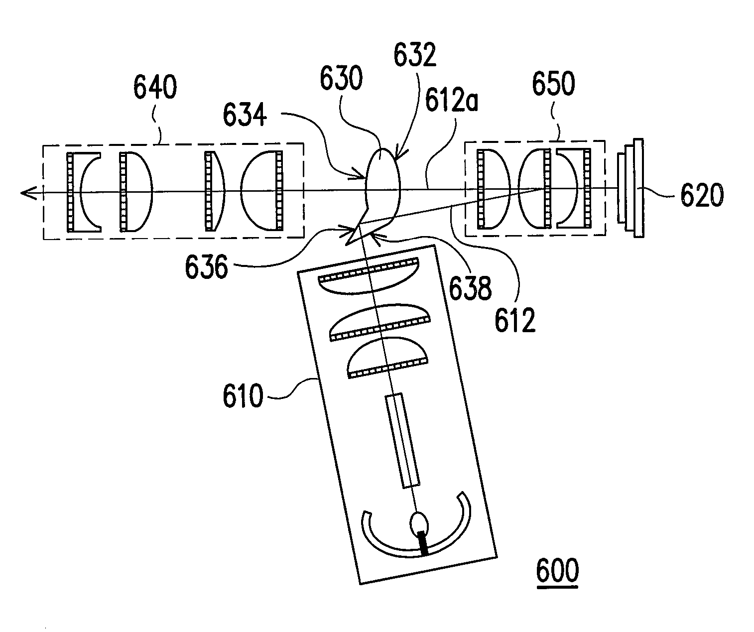
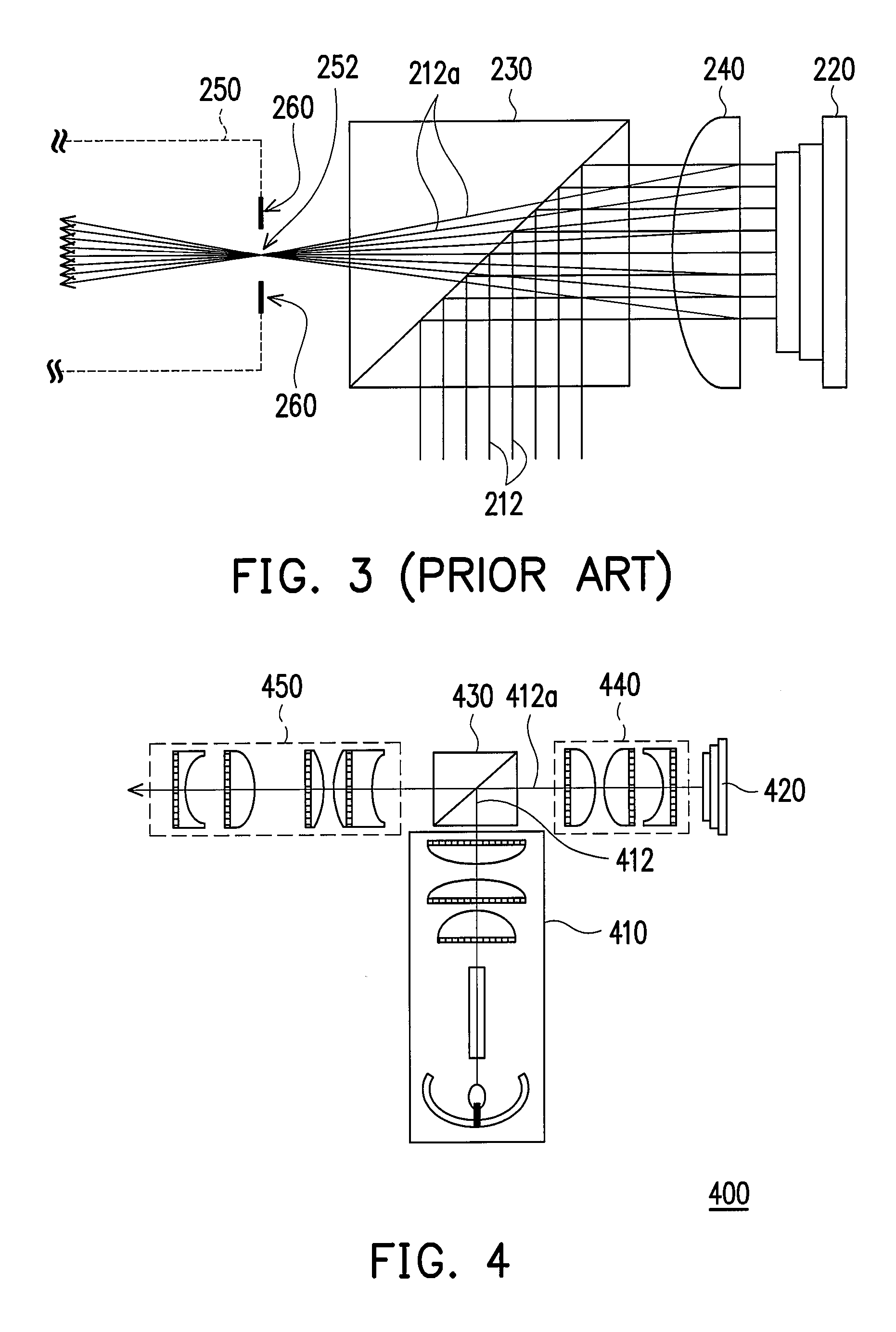
[0024]FIG. 4 shows a schematic structure diagram of an optical projection apparatus according to one embodiment of the present invention. Referring to FIG. 4, the optical projection apparatus 400 comprises an illuminating system 410, a reflective light valve 420, a light deflecting device 430, a lens set 440 and a projection lens set 450. The illuminating system 410 is used for providing a light beam 412, and the reflective light valve 420 is arranged on an optical path of the light beam 412. In the embodiment, the reflective light valve 420 is a digital micro-mirror device (DMD) or a liquid crystal on silicon (LCoS). The light deflecting device 430 is arranged on the optical path of the light beam 412, and located between the illuminating system 410 and the reflective light valve 420. In the embodiment, the light deflecting device 430 is a TIR prism, for example. The lens set 440 is arranged on the optical path of the light beam 412, and located between the reflective light valve 4...


PUM


Abstract

An optical projection apparatus is provided, where a reflective light valve, a light deflecting device and a lens set are arranged on an optical path of the light beam providing by an illuminating system. The light deflecting device is located between the illuminating system and the reflective light valve, and the lens set is located between the reflective light valve and the light deflecting device. When the light beam is incident to the reflective light valve through the light deflecting device and the lens set, the light beam is converted into sub-image beams, and then the sub-image beams are reflected to the lens set. The projection lens set arranged on an optical path of the sub-image beams has a pupil located on the light deflecting device. The lens set converges the sub-image beams on the pupil and then the sub-image beams are incident to the projection lens set for imaging.

Description

CROSS-REFERENCE TO RELATED APPLICATION [0001] This application claims the priority benefit of Taiwan application serial no. 94133943, filed on Sep. 29, 2005. All disclosure of the Taiwan application is incorporated herein by reference. BACKGROUND OF THE INVENTION [0002] 1. Field of the Invention [0003] The present invention relates to a display apparatus. In particularly, the present invention relates to an optical projection display apparatus. [0004] 2. Description of Related Art [0005]FIG. 1 shows an optical projection apparatus 100 disclosed by U.S. Pat. No. 6,784,946. The optical projection apparatus 100 comprises an illuminating system 110, a reflective light valve 120, a prism 130, a lens set 140 and a projection lens set 150. The illuminating system 110 is used for providing a light beam that sequentially passes through the prism 130, the lens set 140, and then is incident to the reflective light valve 120. The reflective light valve 120 is a digital micro-mirror device (DMD)...

Claims


Application Information

Patent Timeline
IPC IPC(8): G03B21/20
CPCG03B21/2066G03B21/208
Inventor CHENG, CHU-MINGCHEN, KUAN-HUNG
Owner YOUNG OPTICS
Why Eureka
Try Eureka