Propellant charge feed or supply means

a technology of propellant charge and feed or supply means, which is applied in the direction of cartridge extractors, ammunition loading, weapons components, etc., can solve the problems of affecting the detonation process in a disadvantageous way, and not ensuring the precise introduction of propellant charge, so as to reduce the speed of propellant charge and save time

Inactive Publication Date: 2007-05-24
KRAUSS MAFFEI WEGMANN GMBH & CO KG
View PDF17 Cites 4 Cited by
  • Summary
  • Abstract
  • Description
  • Claims
  • Application Information

AI Technical Summary

Benefits of technology

[0010] In an advantageous manner, the introducing means can initiate the introduction stroke at a later time than the providing means initiate the feed stroke. Alternatively, the introducing means can perform the introduction stroke after the feed stroke performed by the providing means has been accomplished.
[0012] In an advantageous way, the introducing means and / or the providing means can have a drive configured with changeable parameters that is capable of performing a speed profile. It can for example be beneficial to slow down the speed of the propellant charge advancing means at the moment when it makes contact with the propellant charge. Thereafter, the movement of the propellant charge should nonetheless be realized as fast as possible until the moment in which the propellant charges are introduced, as slowly as possible, into the intended position in the propellant charge chamber.
[0013] The propellant charge advancing means can be provided, in an advantageous way, with one or more suction cups, which couple to the propellant charges by means of suction. Thus, the introduction of the propellant charges into the intended introduction position in the propellant charge chamber is ensured.
[0014] After the propellant charges have been introduced into the intended position in the propellant charge chamber, the introducing means and the providing means return to their initial position. In an advantageous way, the reverse feed stroke and the reverse introduction stroke can take place simultaneously, thus saving time.

Problems solved by technology

It is a disadvantage of the aforementioned configuration that the propellant charge introducing means, which can e.g. be configured as a chain that is stiff on top, does not guarantee a precise introduction of the propellant charge into an intended introduction position in a propellant charge chamber of a weapon tube.
The propellant charges should not lie too far in the rear of the introduction chamber, since, in that case, the closing weapon tube lock could damage them.
Furthermore, if the angle of elevation is small or negative, the propellant charges could be located too far up front after the introduction, thus influencing the process of detonation in a disadvantageous way.

Method used


Image

  • Propellant charge feed or supply means
  • Propellant charge feed or supply means
  • Propellant charge feed or supply means

Examples


first embodiment

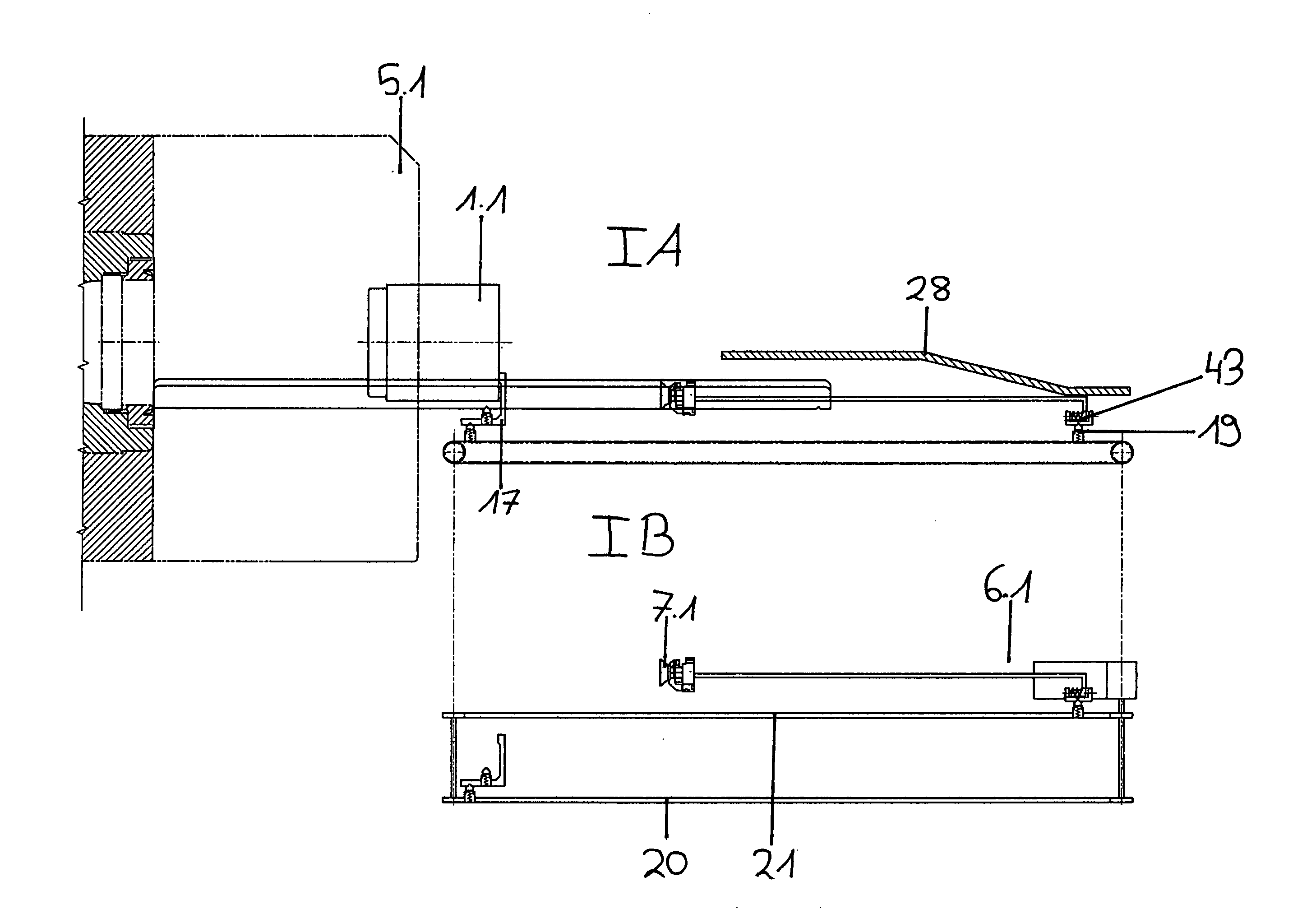
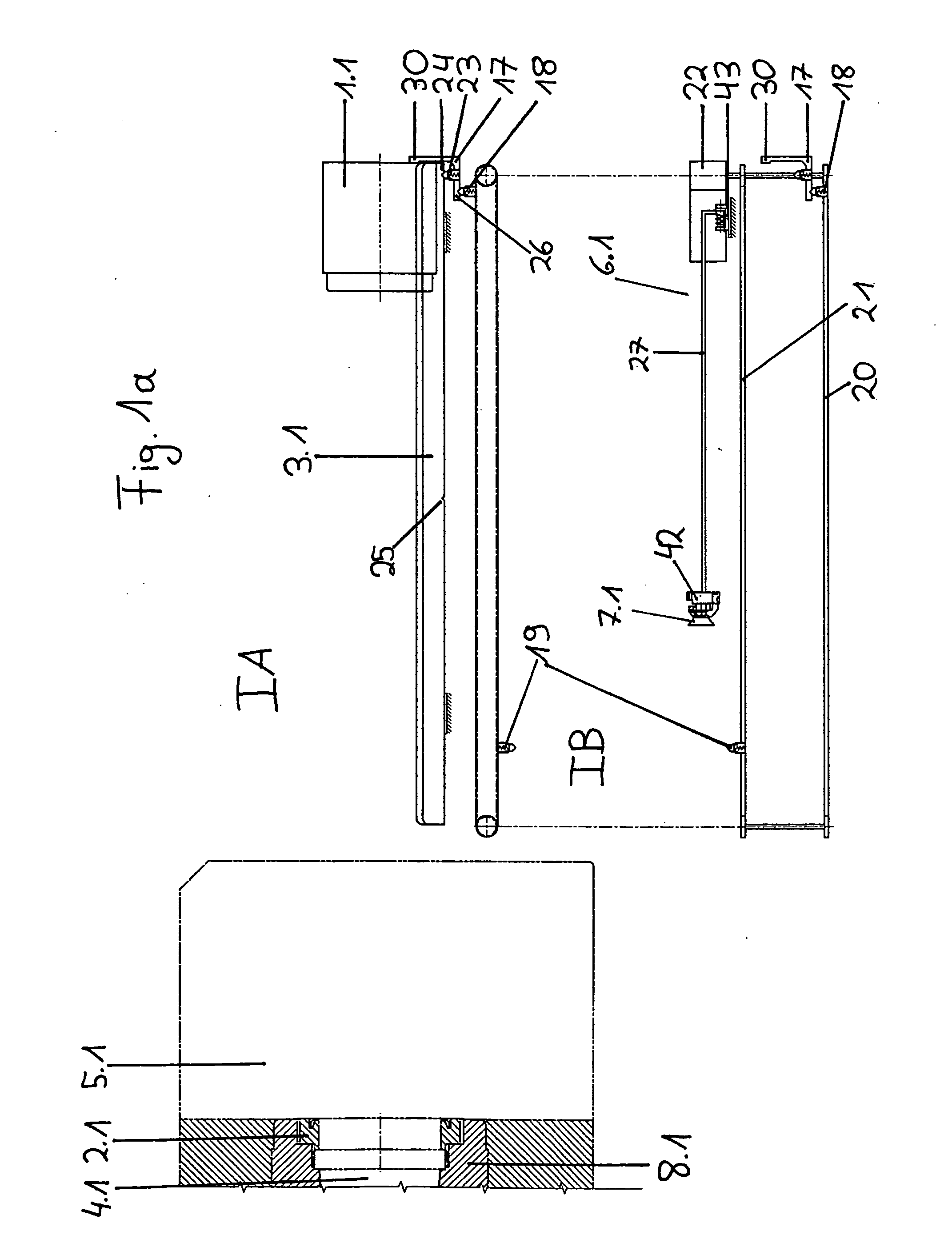
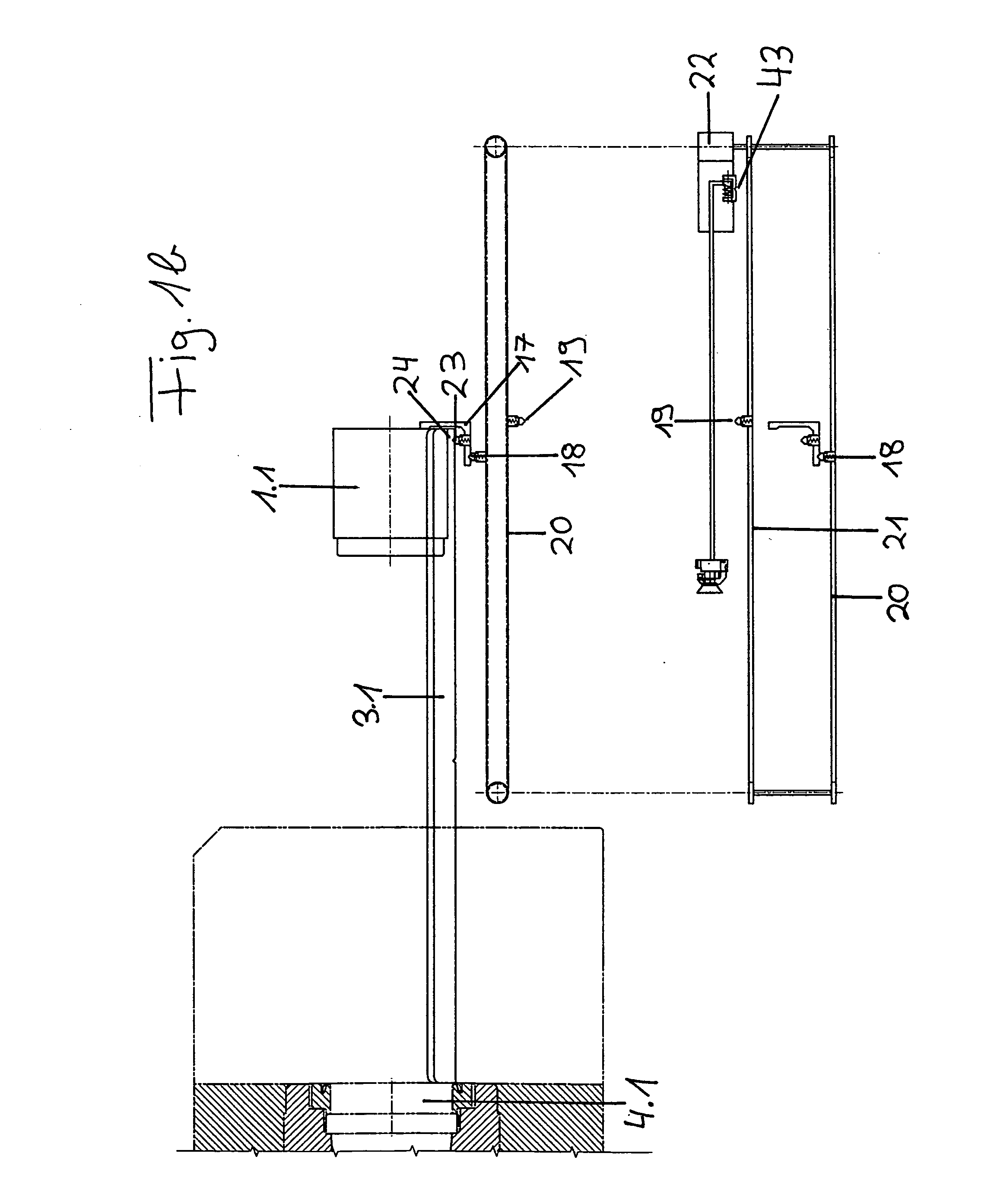
[0041]FIGS. 1a through 1e show the propellant charge feed or supply means. FIGS. 1a through 1e illustrate the sequence of introduction of the propellant charge. FIGS. 1a through 1e show the rear portion of the weapon tube 8.1, the breech assembly 5.1 and the base ring 2.1. In a side view IA, FIGS. 1a through 1e further show a propellant charge 1.1, which is located on a propellant charge feed tray 3.1, for a propellant charge module that is comprised of several individual propellant charges. Located underneath is the view IB, which is a top plan view of the view IA. Due to clarity reasons, the propellant charge 1.1 and the propellant charge feed tray 3.1 are not represented in the view IB. Likewise, not all elements that can be seen in the view IA are shown in the view IB.

[0042] The side view IA shows that the propellant charge feed tray 3.1 is pivoted into a position behind the weapon tube 8.1 in such a way that the propellant charge 1.1 is located coaxial in relation to the axis o...

second embodiment

[0050]FIGS. 2a-2c show the propellant charge feed means. In FIGS. 2a-2c, only one propellant charge 1.2 is represented exemplary for a propellant charge module that is comprised of several individual propellant charges. The propellant charge 1.2 is located on a propellant charge feed tray 3.2, which is pivoted into a position behind the weapon tube 8.2 in such a way that the propellant charge 1.2 is located coaxial in relation to the axis of the bore of the weapon tube 8.2. A propellant charge advancing means 6.2 in the resting position is located below the propellant charge feed tray 3.2. The propellant charge advancing means 6.2 comprises an introduction sled 9 and an elevating element 10 with a suction cup 7.2. The introduction sled 9 is connected to an endless cable pulling means that has a given length. The endless cable pulling means comprises a cable 16 and two cable pulleys 15a and 15b and is connected to a rotational drive 11. The cable pulleys 15a, 15b hereby serve as dire...

third embodiment

[0054]FIGS. 3a-3g show the propellant charge feed means. In this example, the propellant charges 1.3 are combined to a rod of propellant charges that is comprised of six individual propellant charges 1.3.

[0055] The propellant charges 1.3 are located on a propellant charge feed tray 3.3. They are to be moved through the breech assembly 5.3 into the propellant charge chamber 4.3 of the weapon tube 8.3 behind the base ring 2.3.

[0056] For that reason, the propellant charge feed means has a drive 33 that is represented in FIG. 3g. Via a not represented linear spindle, the drive 33 moves a carrier 32, which is connected to the linear spindle by means of a not represented spindle nut. Furthermore, the carrier 32 has a carrier finger 34 and a not represented arresting part that engages into a not represented engagement element in the propellant charge feed tray 3.3. Hence, the drive 33 can move the propellant charge feed tray 3.3 via the linear spindle and the carrier 32.

[0057] The propel...


PUM


Abstract

A propellant charge feed or supply system for automatic introduction of modular propellant charges into the weapon tube of a heavy weapon having a breech assembly and a propellant charge chamber in front of the breech assembly. An oblong propellant charge feed tray is pivotable into position behind the weapon tube such that propellant charges disposed on the propellant charge feed tray are disposed coaxial relative to the axis of the bore of the weapon tube. A providing device is adapted during a feed stroke to move the propellant feed tray into the breech assembly up to the propellant charge chamber. An introduction device is adapted during an introduction stroke to move the propellant charges from the feed tray into the propellant charge feed tray.

Description

BACKGROUND OF THE INVENTION [0001] The present invention relates to a propellant charge feed or supply means. [0002] The propellant charge feed means is a part of a fully automatic firing module on a combat vehicle having a heavy weapon. [0003] A fully automatic firing module has several advantages in comparison with a firing module that has to be operated manually. For example, the automation enables the personnel that operate the weapon to be spatially separated from the weapon, the aiming mechanism, the projectile feed means, the propellant charge feed means and the ammunition. The existing structure for ballistic protection can hence be reduced to the space of the protective compartment for the personnel, in other words, the control station. By separating the operating personnel and the firing module, the number of crewmembers can be reduced to a minimum. Furthermore, the total weight of the combat vehicle can be reduced. The separation of the personnel and the firing module fur...

Claims


Application Information

Patent Timeline
Patent Type & Authority Applications(United States)
IPC IPC(8): F41A9/16
CPCF41A9/375F41A9/43
Inventor SPORK, ROLANDSCHEIDEMANN, GEORGSUSS, SIEGFRIEDGRUNEWALD, JENS
Owner KRAUSS MAFFEI WEGMANN GMBH & CO KG
Why Eureka
Try Eureka