Dome cover, camera device, injection molding die, and injection molding method

a technology of injection molding die and dome cover, which is applied in the direction of camera body details, instruments, camera filters, etc., can solve the problems of deterioration of images and differences in thickness, and achieve excellent mold releasability from the molded dome cover

Active Publication Date: 2018-01-18
FUJIFILM CORP
View PDF2 Cites 2 Cited by
  • Summary
  • Abstract
  • Description
  • Claims
  • Application Information

AI Technical Summary

Benefits of technology

[0045]Additionally, according to the present aspect, the outer diameter molding part that molds the outer diameter of the first molding die, and the inner diameter molding part that molds the inner diameter of the second molding die become continuously wide from the top section molding part. Accordingly, in the present aspect, the mold releasibility from the molded dome cover is excellent.

Problems solved by technology

However, if the thickness of the skirt section is uniformly made small, a difference in thickness may occur in a boundary surface between the curved section and the skirt section, and deterioration of an image may occur due to the light that passes through the boundary surface.

Method used


Image

  • Dome cover, camera device, injection molding die, and injection molding method
  • Dome cover, camera device, injection molding die, and injection molding method
  • Dome cover, camera device, injection molding die, and injection molding method

Examples


first embodiment

[0066]The first embodiment of the invention will be described.

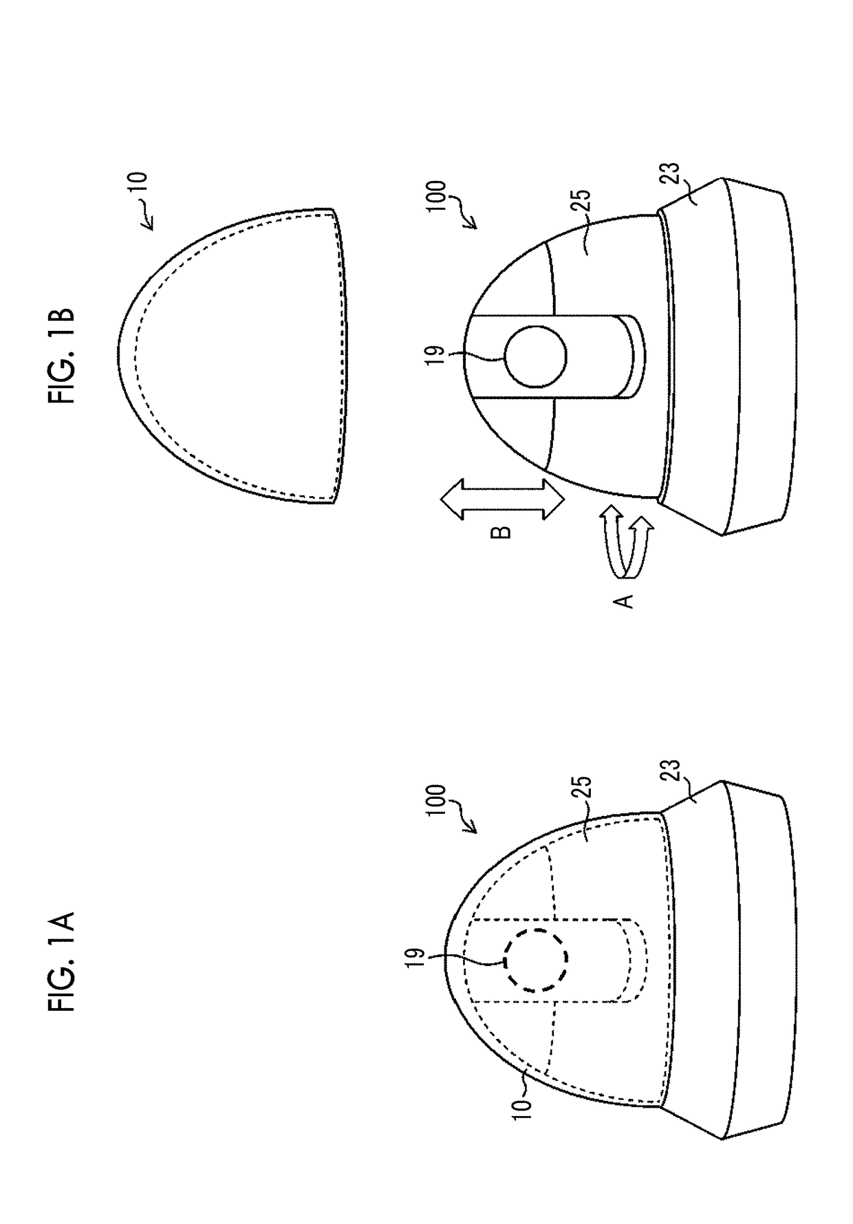
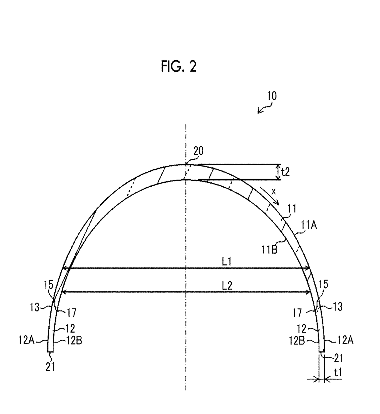
[0067]FIG. 2 is a longitudinal sectional view of the dome cover 10 illustrated in FIGS. 1A to 1B, and FIG. 3 is a plan view of the dome cover 10 illustrated in FIGS. 1A to 1B.

[0068]As illustrated in FIG. 2, the dome cover 10 has a shape including a curved section 11 having a curved shape and a skirt section 12 having a cylinder shape, and as illustrated in FIG. 3, an opening end section 21 has a circular shape. In addition, the shape of the opening end section 21 is not limited to the circular shape, and shapes according to shapes or applications of the camera device 100 to which the dome cover 10 is attached can be adopted.

[0069]The curved section 11 has a front surface 11A and a back surface 11B, and is formed in a curved shape by the front surface 11A of the curved section 11 and the back surface 11B of the curved section 11. Here, the “curved shape” means the shape of a smooth convex surface. For example, the curved s...

second embodiment

[0104]Next, a second embodiment of the dome cover 10 will be described..

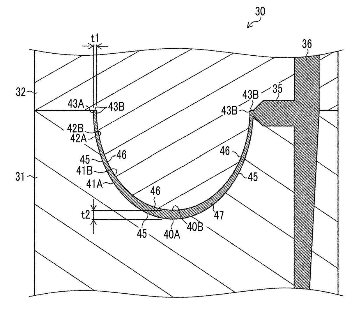
[0105]FIG. 8 is a longitudinal sectional view of the dome cover 10, illustrating the dome cover 10 of the second embodiment. The portions that have been already described in FIG. 2 will be designated by the same reference signs, and the description thereof will be omitted.

[0106]The dome cover 10 of the second embodiment includes the curved section 11 having a curved shape and the skirt section 12 having a cylinder shape.

[0107]The curved section 11 has a semi-spherical shape formed by the front surface 11A and the back surface 11B of the curved section 11. Additionally, the thickness at the top section 20 of the curved section 11 is t2, the thickness at the connection end section 15 (boundary surface 13) of the curved section 11 is also t2, and the thickness of the curved section 11 is uniform. That is, the thickness at the curved section 11 is t2 over the whole region of the curved section 11, and is different f...


PUM

PropertyMeasurementUnit
thicknessaaaaaaaaaa
inner diameteraaaaaaaaaa
outer diameteraaaaaaaaaa

Abstract

The invention provides a dome cover, a camera device, an injection molding die, and an injection molding method in which generation of a weldline is suppressed and deterioration of an acquired image is suppressed. In one aspect of the invention, a dome cover is a dome cover that covers a camera. The dome cover includes a curved section having a curved shape and a skirt section having a cylinder shape and has a top section at the curved section and an opening end section at the skirt section. The thickness of the dome cover is largest at the top section and smallest at the opening end section, and continuously decreases from the top section toward the opening end section. The inner diameter and the outer diameter of the dome cover continuously increase from the top section toward the opening end section.

Description

CROSS-REFERENCE TO RELATED APPLICATIONS[0001]The present application is a Continuation of PCT International Application No. PCT / JP2015 / 083601 filed on Nov. 30, 2015 claiming priority under 35 U.S.C. §119(a) to Japanese Patent Application No. 2015-064775 filed on Mar. 26, 2015. Each of the above applications is hereby expressly incorporated by reference, in their entirety, into the present application.BACKGROUND OF THE INVENTION1. Field of the Invention[0002]The present invention relates to a dome cover, a camera device, an injection molding die, and an injection molding method, and particularly, the technique for a dome cover in which the thickness of the dome cover is adjusted.2. Description of the Related Art[0003]Pan tilt cameras capable of changing an imaging direction have been known from the past. The pan tilt cameras may be covered with a dome cover from viewpoints of dust-proofing, drip-proofing, and failure prevention.[0004]Various shapes are suggested from viewpoints of th...

Claims


Application Information

Patent Timeline
Patent Type & Authority Applications(United States)
IPC IPC(8): G03B17/56B29C45/27B29C45/00B29L31/00
CPCG03B17/568B29C45/2708B29C2045/0037B29L2031/773G03B17/56G03B11/00G03B17/02H04N23/51
Inventor WATANABE, SEIICHI
Owner FUJIFILM CORP
Why Eureka
Try Eureka