Display device and electrical appliance using the same

a technology of display device and electrical appliance, which is applied in the direction of cathode ray tube/electron beam tube, instruments, electrical discharge tube, etc., can solve the problems of large impairment of the visual affecting the quality of the display device, and involving complex process and construction, etc., and achieves the effect of high quality

Inactive Publication Date: 2007-03-01
HITACHI LTD
View PDF69 Cites 100 Cited by
  • Summary
  • Abstract
  • Description
  • Claims
  • Application Information

AI Technical Summary

Benefits of technology

[0036] The invention can realize a display device, which comprises a protective plate arranged on a front surface of a display panel and an optically transparent layer between the protective plate and the display panel and i

Problems solved by technology

That is, with a display device provided with a protective plate, unnecessary interfacial reflection is generated on a front surface and a back surface of the protective plate, so that visibility of the display device is considerably impaired especially in the case where surrounding environment is bright.
In the case where an optically transparent layer made of a liquid material is filled as an external light reflection preventive layer between a protective plate and a display device, measures to surround a periphery of the layer with a sealing material becomes necessary in order to prevent leakage of the optically transparent layer from between the protective plate and the display device, thus involving complexity in process and construction.
Several problems are caused in application of a sheet-shaped material as an optically transp

Method used


Image

  • Display device and electrical appliance using the same
  • Display device and electrical appliance using the same
  • Display device and electrical appliance using the same

Examples


Embodiment Construction

[0067] Embodiments of the invention will be described hereinafter with reference to the drawings.

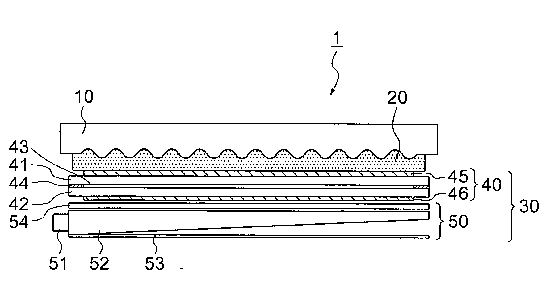
[0068]FIG. 1 is a schematic view showing outline of a cross sectional structure of an embodiment of a display device of the invention. The display device 1 comprises a display panel 30, a protective plate 10 arranged on a front surface of the display panel, and an optically transparent layer 20 filled between the protective plate 10 and the display panel 30.

[0069] Liquid crystal display panels, organic electroluminescence panels, etc. can be used as the display panel 30. Also, these display panels are of a passive drive type and of an active matrix drive type, but of which detailed structures and operations thereof are well known and therefore an explanation therefor is omitted herein.

[0070] The embodiment will be described with respect to the case where a liquid crystal display panel is used for the display panel 30 but the invention is not limited thereto.

[0071] The liquid crystal ...


PUM


Abstract

A liquid crystal display device comprising a pair of substrates, a liquid crystal display panel having a liquid crystal layer positioned between the substrates, a transparent protective plate arranged on a front surface side of the display panel, and an optically transparent layer between the display panel and the protective plate, and wherein the protective plate includes fine concavity and convexity configurations on at least a surface thereof toward the display panel.

Description

BACKGROUND OF THE INVENTION [0001] The present invention relates to a display device, and more particular, to a display device provided on a front surface side thereof with a transparent protective plate. Further, the present invention relates to an appliance provided with such display device. [0002] As display devices mounted on portable appliances such as portable telephones, etc. there are liquid crystal display devices and organic electroluminescence display devices. While these display devices are of a passive drive type and of an active matrix drive type, detailed constructions and operations thereof are well known and so an explanation therefor is omitted. [0003] In the case where these display devices are mounted on portable appliances such as portable telephones, etc., a transparent protective plate is provided on a front surface of a display device in order to prevent an action of a mechanical force applied from outside from disordering or breaking display. [0004] Since a ...

Claims


Application Information

Patent Timeline
IPC IPC(8): G02F1/1333
CPCG02F1/1335G02F1/1333G02F1/133308G02F2202/28G02F1/133331
Inventor ADACHI, MASAYASUGIBAYASHI, MAKIKOOHSHIMA, TETSUYAKONDO, KATSUMISASAKI, HIROSHI
Owner HITACHI LTD
Why Eureka
Try Eureka