
Shift control device for bicycle

a technology of shifting control and bicycle, which is applied in the direction of linear movement shafts, shafts and bearings, cycle equipment, etc., can solve the problems of inability to change the speed of the transmission device, the control device is not ergonomically designed, etc., and achieves the effect of convenient operation

Inactive Publication Date: 2011-10-11
TIEN HSIN INDS
View PDF3 Cites 2 Cited by
  • Summary
  • Abstract
  • Description
  • Claims
  • Application Information

AI Technical Summary

Benefits of technology

[0011]The operation of the shift-down controller enables the first actuating member to cause the first pawl of the transmission control assembly to engage with the second engaging section and the second actuating member to cause the second pawl of the transmission control assembly to disengage from the second engaging section, and enables further movement of the shift-down controller to cause travel of the locking member in a second direction reverse to the first direction.
[0012]It is therefore an object of the present invention to provide a bicycle shift device that is easily operable.
[0013]It is a further object of the present invention to provide a bicycle device that shifts up / shifts down bicycle speed transmission precisely.

Problems solved by technology

However, the control device is not an ergonomic design, because the user has to apply a relatively substantial force to execute the speed transmission.
Furthermore, if the shift control device is not operated with sufficient force, it often happens that the change in speed transmission is not successful.

Method used


Image

  • Shift control device for bicycle
  • Shift control device for bicycle
  • Shift control device for bicycle

Examples


Embodiment Construction

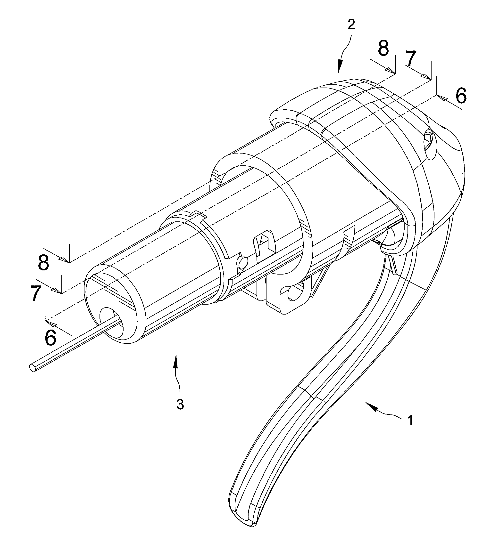
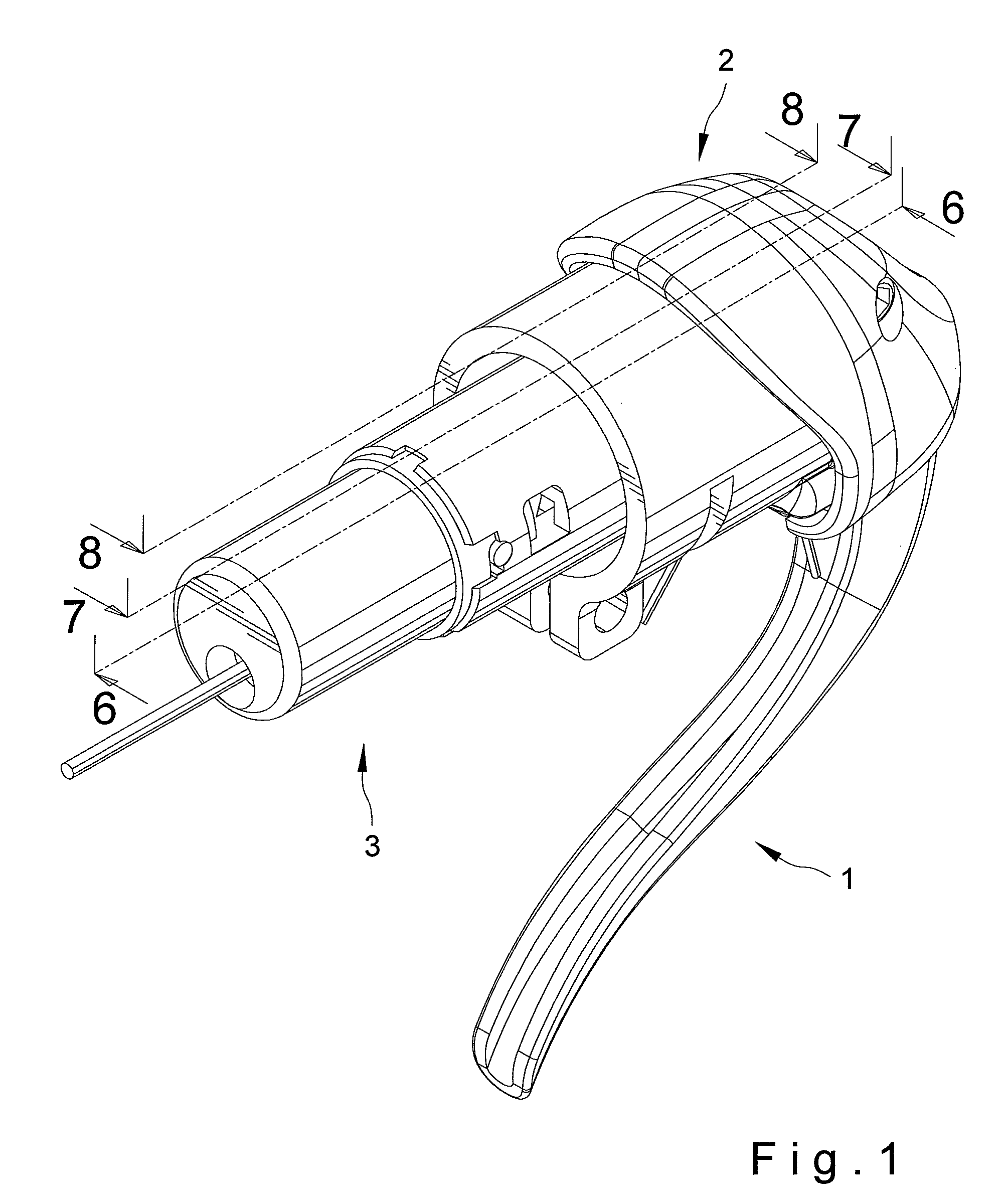
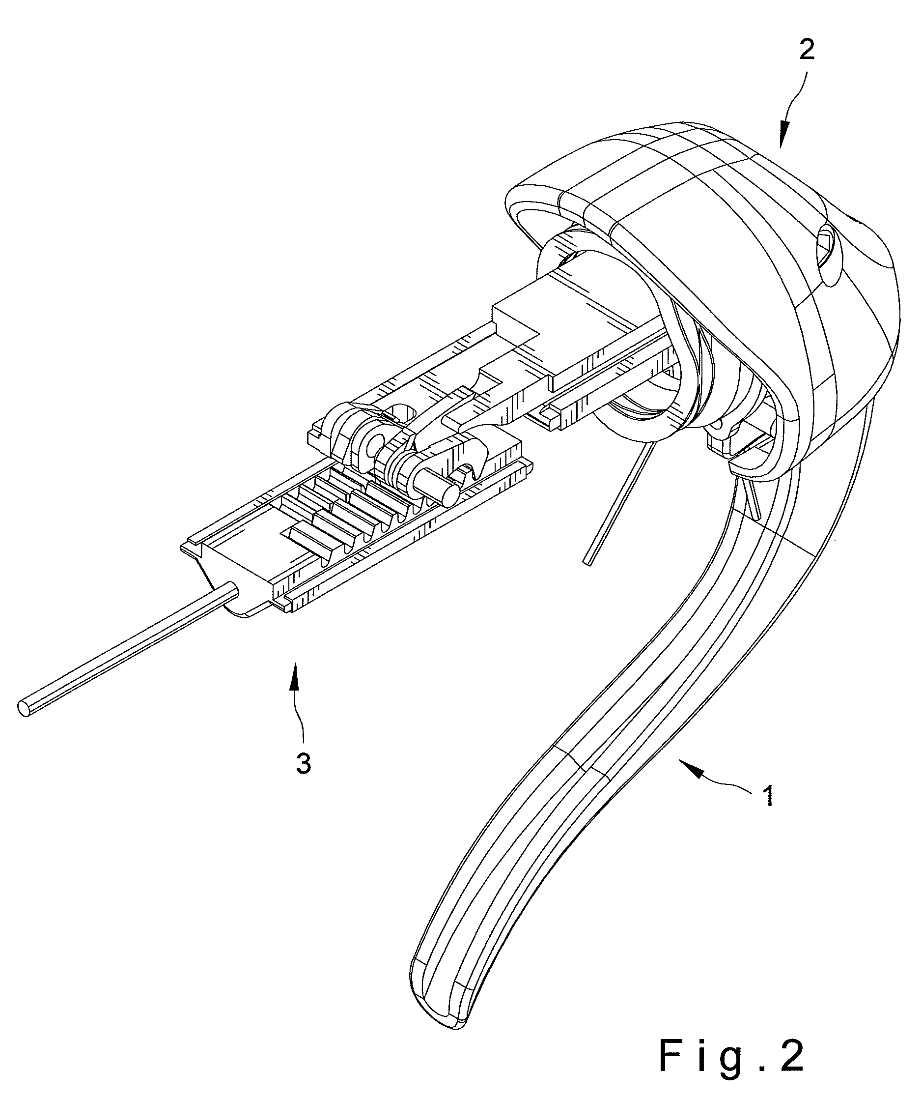
[0033]FIGS. 1 and 2 show a perspective view of a shift control device in accordance with the present invention. The shift control device can change bicycle speed transmission and includes a shift-up control apparatus 1, a shift-down control apparatus 2 and a transmission control assembly 3.

[0034]Referring to FIGS. 3 through 6, the shift-up control apparatus 1 includes a shift-up controller 10, a first link member 20 and a first pawl 30. The shift-up controller 10 includes a first end 101 and a second end 102. A user puts his / her hand on the first end 101 to control the shift-up controller 10. The second end 102 includes two connecting lobes 11 each has a first hole 12 and a second hole 13. Additionally, the two connecting lobes 11 receive the first link member 20 and an elastic member 14 therebetween.

[0035]An axle 15 is inserted through the elastic member 14 to connect with the shift-up controller 10, and the axle 15 has two ends received by the two second holes 13, respectively. In...


PUM


Abstract

A shift control device includes a shift-up control apparatus, a shift-down control apparatus and a transmission control assembly. The shift-up control apparatus includes an operable shift-up controller, a first link member connected with the shift-up controller and a first pawl pivotally mounted on the first link member. The shift-down control apparatus includes an operable shift-down controller and a second link member connected with the shift-down controller. The second link member includes first and second actuating members. The transmission control assembly includes a locking member, a housing assembly and first and second pawls. The locking member is moveable in the housing at various positions for various bicycle speed transmissions and includes first and second engaging sections. The first engaging section is selectively engaged by the first pawl of the shift-up control apparatus and the second engaging section is selectively engaged by the first and second pawls of the transmission control assembly.

Description

BACKGROUND OF THE INVENTION[0001]1. Field of the Invention[0002]The present invention relates to a shift control device for changing speed transmission for a bicycle and, in particular, to an easily operable shift control device.[0003]2. Description of the Related Art[0004]It is common that bicycle shift control devices are installed on handlebars of bicycles. The shift control device has a lever for a user to change speed transmission of the bicycle, and the user generally uses his / her thumb to operate the lever. However, the control device is not an ergonomic design, because the user has to apply a relatively substantial force to execute the speed transmission. Furthermore, if the shift control device is not operated with sufficient force, it often happens that the change in speed transmission is not successful.[0005]The present invention is, therefore, intended to obviate or at least alleviate the problems encountered in the prior art.SUMMARY OF THE INVENTION[0006]According to th...

Claims


Application Information

Patent Timeline
Patent Type & Authority Patents(United States)
IPC IPC(8): F16C1/10
CPCB62K23/06B62M25/04Y10T74/20438
Inventor CHIANG, DOUGLAS
Owner TIEN HSIN INDS
Learn More