Overrunning clutch

Inactive Publication Date: 2007-05-31
SCHAEFFLER TECH AG & CO KG
View PDF8 Cites 8 Cited by
  • Summary
  • Abstract
  • Description
  • Claims
  • Application Information

AI Technical Summary

Benefits of technology

[0003] The invention is based on the object of specifying a frictionally engaging overrunning clutch which,

Problems solved by technology

The overall cage design of the kn

Method used


Image

  • Overrunning clutch
  • Overrunning clutch
  • Overrunning clutch

Examples


Example

DETAILED DESCRIPTION OF THE DRAWINGS

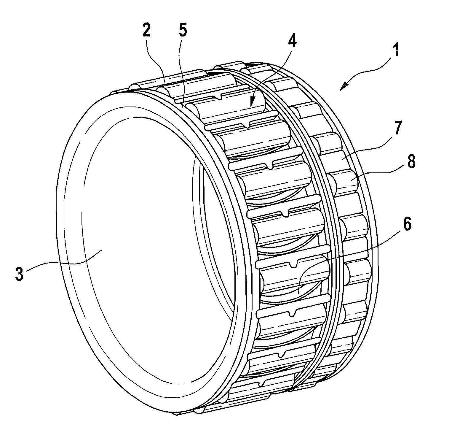
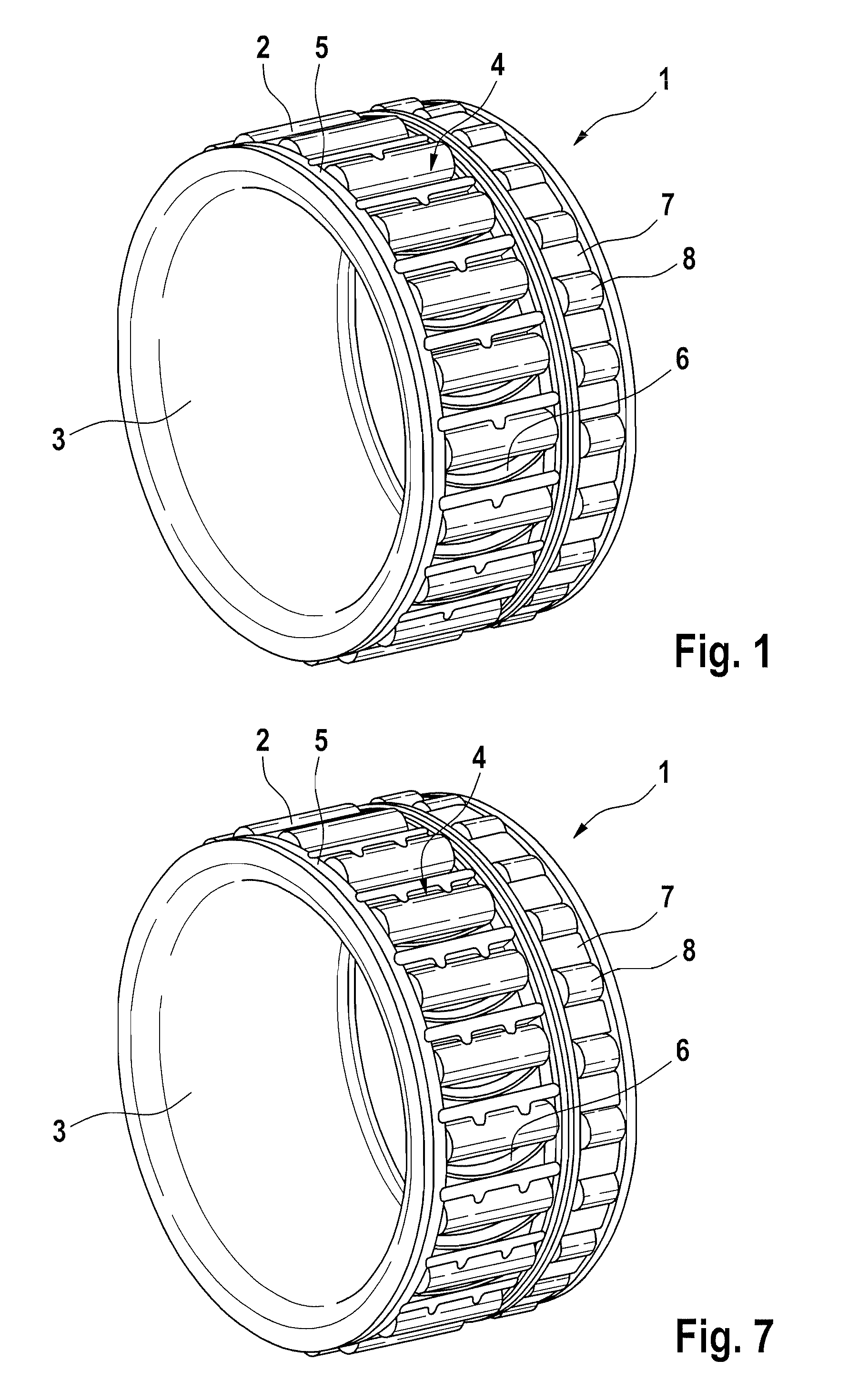
[0016]FIG. 1 illustrates the significant parts of an overrunning clutch 1 with the exception of an outer ring. Clamping bodies 2 which are embodied as rollers or needles are situated in an annular space between an inner raceway 3 and the outer raceway which, for clarity, is not illustrated. The clamping rollers 2 are guided individually in cut-outs 4 of a cage 5 which is produced from plastic. The inner raceway 3 and / or the outer raceway has, in a manner known per se, clamping ramps (not visible in the illustration) to ensure the desired overrunning function. Spring elements 6, which each project into a cut-out 4, are provided to press the clamping body 2 against the clamping ramps in a defined manner.

[0017] Situated axially adjacent to the cage 5 which guides the clamping bodies 2 is a further cage 7 in which cylindrical roller bodies 8 are guided, so that a rolling bearing arrangement is provided between the inner raceway 3 and the outer racew...


PUM


Abstract

In an overrunning clutch (1), an annular space is formed between an inner raceway (3) and an outer raceway, in which annular space is arranged a cage (5) which has cut-outs (4) for holding clamping bodies (2), with each cut-out (4) being delimited by transverse webs (10) which run in the axial direction, and with in each case one spring element (6), which projects into a cut-out (4) and exerts a force on a clamping body (2), adjoining the transverse webs (10). At that side of the transverse web (10) which faces away from the spring element (6), at least one retaining lug (4), which serves to retain a clamping body (2), extends into a cut-out (4).

Description

FIELD OF THE INVENTION [0001] The present invention relates to a frictionally engaging overrunning clutch having an annular space formed between an inner raceway and an outer raceway, in which annular space are arranged clamping bodies which are held in a cage. BACKGROUND OF THE INVENTION [0002] An overrunning clutch of the type mentioned in the introduction is, for example, known from DE 1 142 254 B. Two cages, which are provided for guiding the clamping bodies, are arranged in the annular space of said overrunning clutch, one of which cages is embodied as a ring made from resiliently elastic sheet metal. Said cage has cut-outs which are separated from one another by transverse webs which are arranged one behind the other in the peripheral direction and are arranged in the axial direction of the overrunning clutch. A resilient tongue extends from a transverse web into each cut-out, said tongue in each case exerting a force on a clamping body. The entire cage, which is manufactured ...

Claims


Application Information

Patent Timeline
IPC IPC(8): F16D41/07
CPCF16D41/067F16D2041/0605
Inventor ALTMANN, FRIEDER
Owner SCHAEFFLER TECH AG & CO KG
Why Eureka
Try Eureka