Pelletizing device with a cutting rotor

Inactive Publication Date: 2015-07-23
AUTOMATIK PLASTICS MASCH GMBH
View PDF8 Cites 6 Cited by
  • Summary
  • Abstract
  • Description
  • Claims
  • Application Information

AI Technical Summary

Benefits of technology

[0030]It is particularly expedient to the simplification of production and assembly if each recess has the same inner contour over its length, since the clamping devices are even easier to manufacture and to insert.
[0031]In a preferred embodiment of the invention, the recess of the cutting blade extends from one flat end of the cutting blade to the other flat end of the cutting blade. The clamping device has the same length as the blade, which facilitates ideal stabilization and clamping effect along the entire length of the clamping device.
[0032]If the circle-segment cross section of each recess in the cutting blade is offset radially outwards with respect to the circle-segment cross section of the opposite recess in the rotor body, by engaging the clamping device the clamping force that is effective on the cutting blade is pushing the cutting blade radially inwards. This results in a tighter, more secure fit.
[0033]Preferably the clamping sleeves

Problems solved by technology

However, this disclosure has the drawback that two clamping elements have to be inserted from two sides in order to guarantee a constant distribution of the clamping force, sufficient clamping force and stability.
This makes both the production of the

Method used


Image

  • Pelletizing device with a cutting rotor
  • Pelletizing device with a cutting rotor
  • Pelletizing device with a cutting rotor

Examples


Embodiment Construction

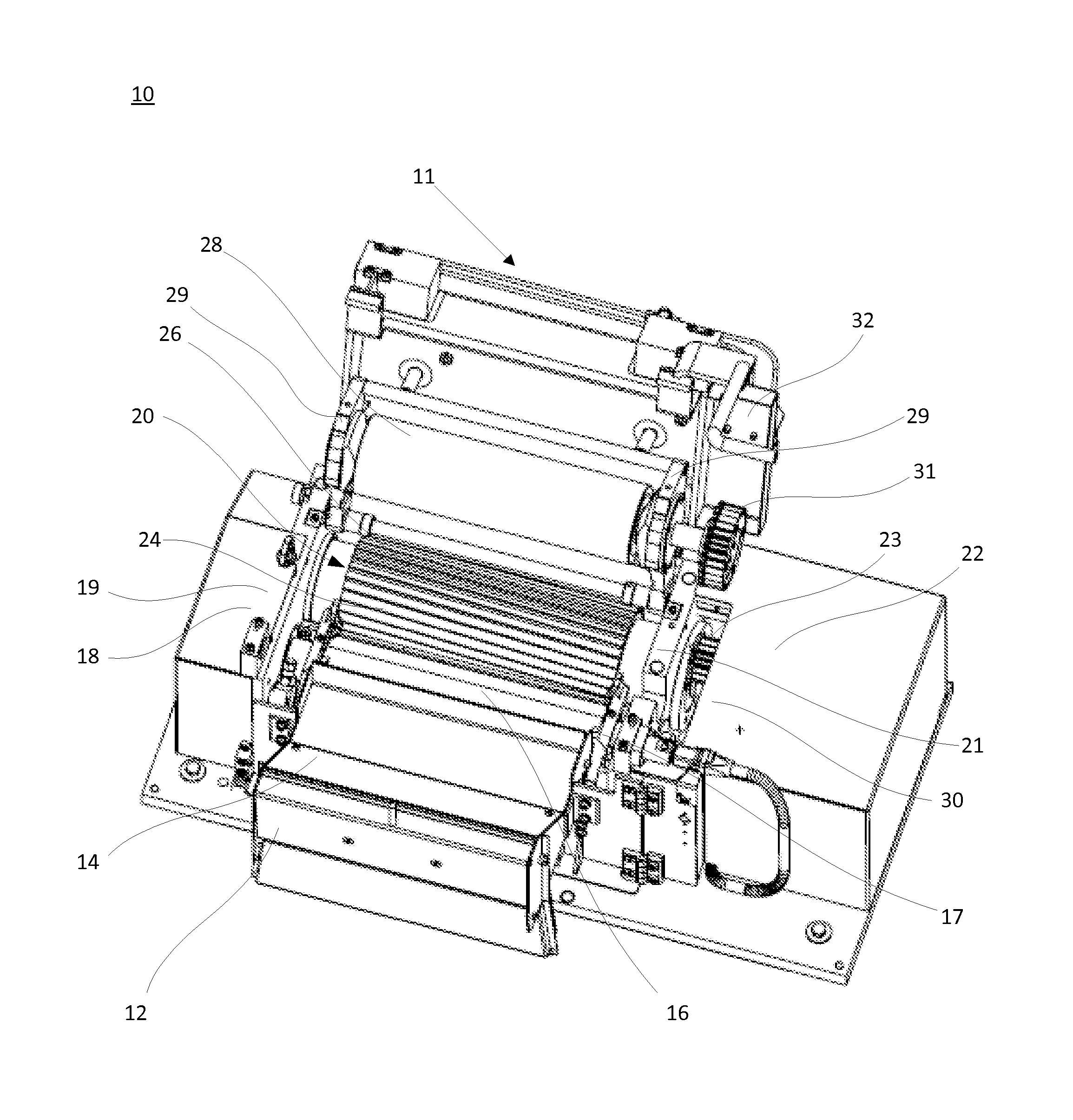
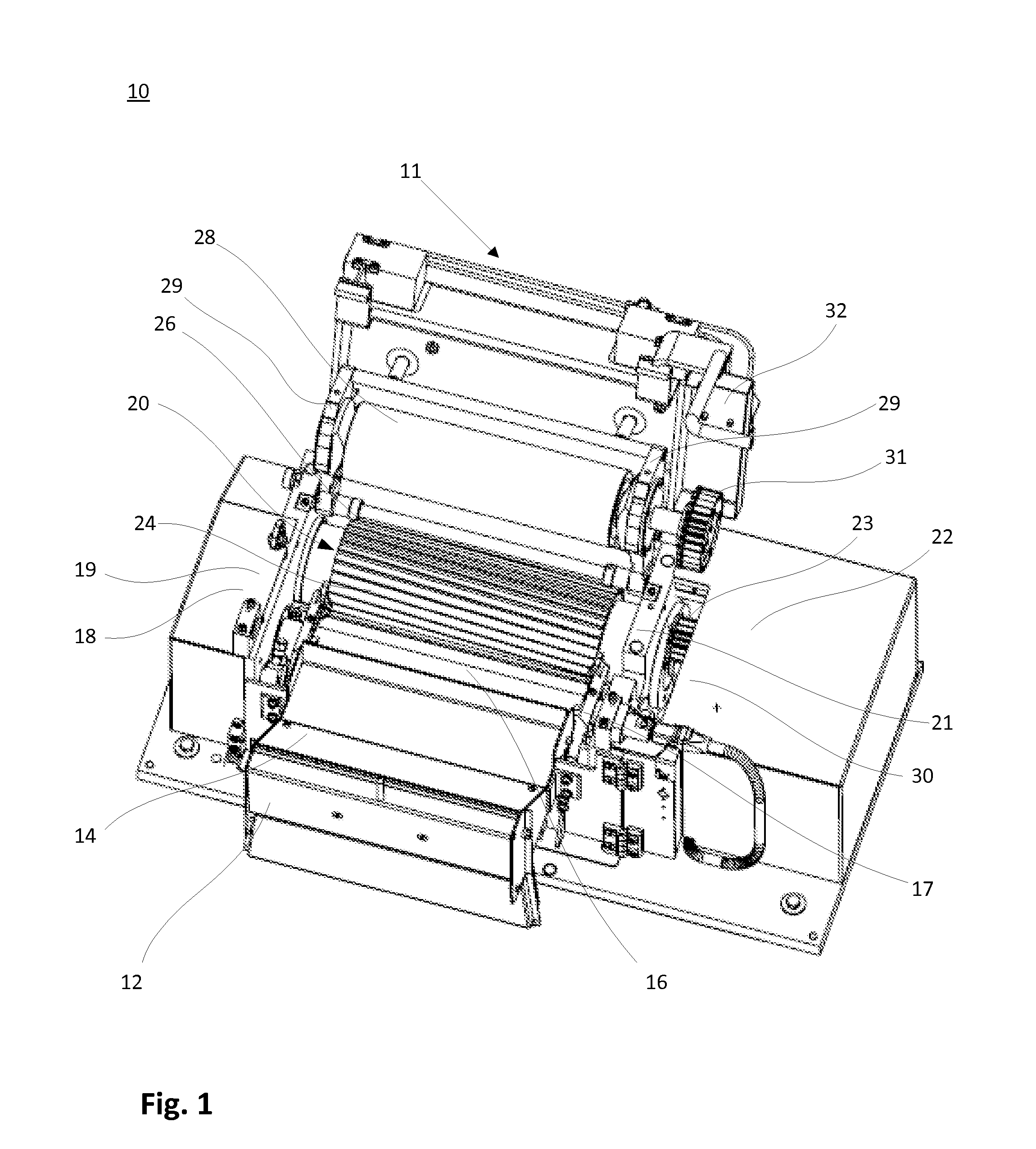
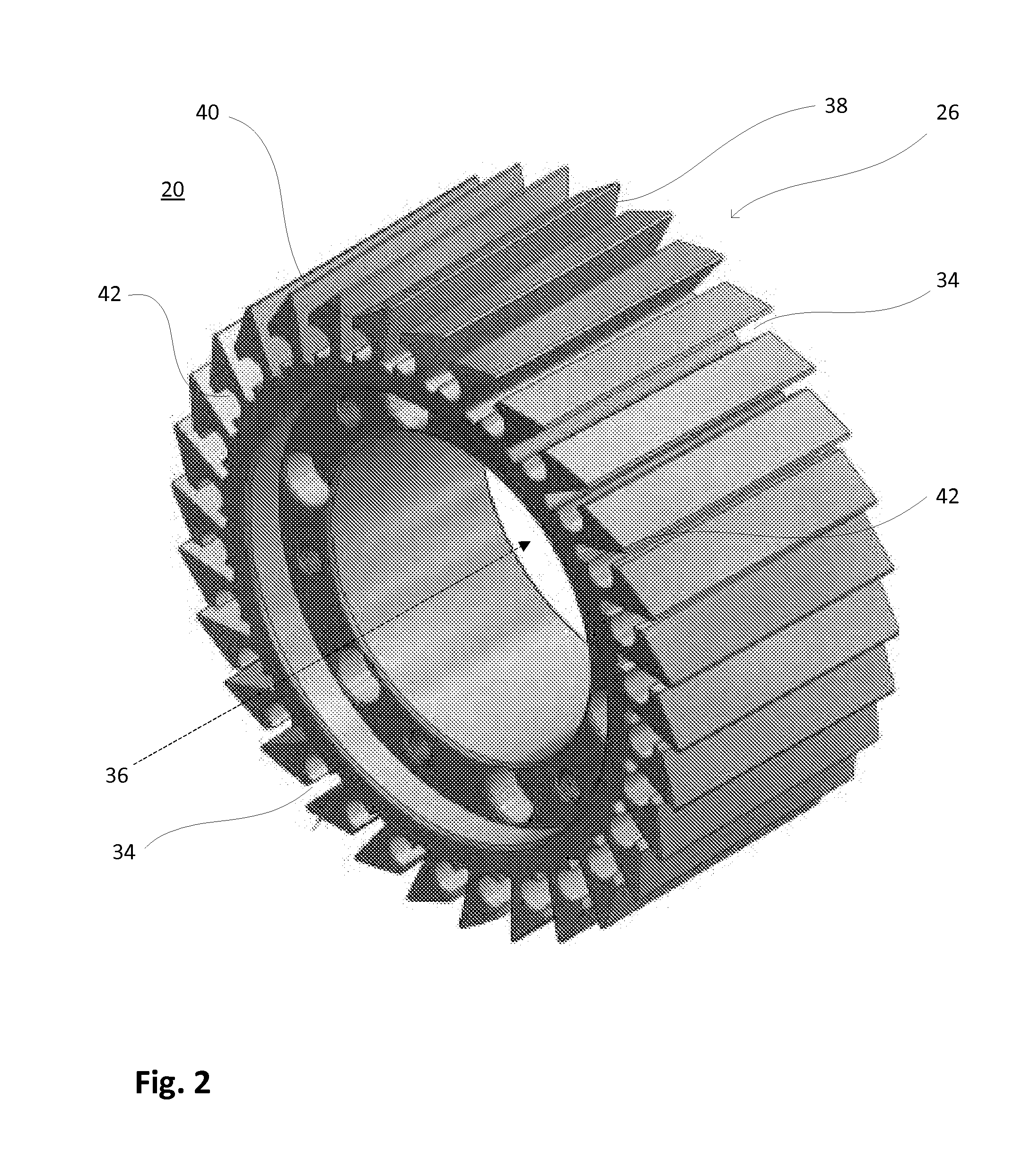
[0044]FIG. 1 shows an embodiment of the pelletizing device 10. For better illustration, the device is shown with an open top cover, henceforth called cutting chamber flap 11. At its front, the pelletizing device 10 has a housing flap 12 through which plastic fibre strands (not shown in this figure) are fed into an inlet chute 14. Subsequently, the plastic fibre strands are drawn further into the pelletizing device by two feed rolls 16, 28. The lower feed roll 16 is mounted on a bearing 17 and driven by a gear wheel 19 and a feed roll drive 18. The upper feed roll 28 is mounted on a bearing 29, which is attached to the cutting chamber flap 11, and driven by a gear wheel 31 and a feed roll drive 30. After passing the feed rolls 16, 28 the plastic fibre strands reach a cutting rotor 20, which is mounted on a bearing 21 and driven by a gear wheel 23 and a rotor drive 22. The cutting rotor 20 is equipped with cutting blades 24 on its circumferential surface 26 that cut the plastic fibre ...


PUM

PropertyMeasurementUnit
Angleaaaaaaaaaa
Lengthaaaaaaaaaa
Radiusaaaaaaaaaa

Abstract

The invention refers to a pelletizing device for cutting plastic strands into pellets having a cutting rotor (20) which is rotated by a drive system (22), and cutting blades (24) distributed over a circumference (26) of the cutting rotor (20) having cutting edges (78), root areas (44) of which cutting blades (24) are arranged in grooves (34) in the rotor body (20), each cutting blade (24) having a recess (46) parallel to the cutting edge (78), which recesses (46) are covered by one of the grooves (34) to receive and interact with one clamping device (48) being held in an opposite recess (42) in the rotor body (20), wherein each clamping device (48) comprises a radially extendable clamping sleeve (50) and a spreading device (58, 64, 70) to widen the clamping sleeve (50) at least radially with respect to the clamping sleeve (50). The invention is characterized in that only one clamping sleeve (50) per each cutting blade (24) is provided in the groove (34),
said recess (46) of the cutting blade (24) extends from one flat end (80) of the cutting blade (24) at least close to the other flat end (81) of the cutting blade (24), said clamping sleeve (50) having an outer contour (52) which fits within the recess (46) in the cutting blade (24) and the opposite recess (42).

Description

BACKGROUND[0001]1. Field[0002]The invention refers to a pelletizing device with a cutting rotor.[0003]2. Related Art[0004]Pelletizing devices for cutting plastic fibre strands into pellets with a cutting rotor are widely used in combination with plastic extruding devices. Generally, a cylindrical cutting rotor equipped with cutting blades rotates at high speed and provides plastic pellets for further processing steps. The cutting blades are distributed over the entire circumference of the rotor and connected to the rotor in a way that guarantees safe operation and low wear.[0005]As opposed to earlier solutions, in which the cutting blades were soldered into grooves on the surface of the rotor body, it has been suggested that the blades are clamped into the grooves in different ways, e.g. mechanically or hydro-mechanically, so that the blades can be exchanged with less effort.[0006]The publication U.S. Pat. No. 6,386,469 B1 has disclosed a granulating device with a cutting rotor with...

Claims


Application Information

Patent Timeline
IPC IPC(8): B26D7/26B02C18/14B02C18/18B29C47/00
CPCB26D7/2614B29C47/0066B29L2031/772B02C18/186B02C18/148Y10T83/7747B29B9/06B29C48/0022
Inventor HARMON, TIM
Owner AUTOMATIK PLASTICS MASCH GMBH
Why Eureka
Try Eureka