

Tape drive
- Summary
- Abstract
- Description
- Claims
- Application Information
AI Technical Summary
Benefits of technology
Problems solved by technology
Method used
Image

Examples
Embodiment Construction
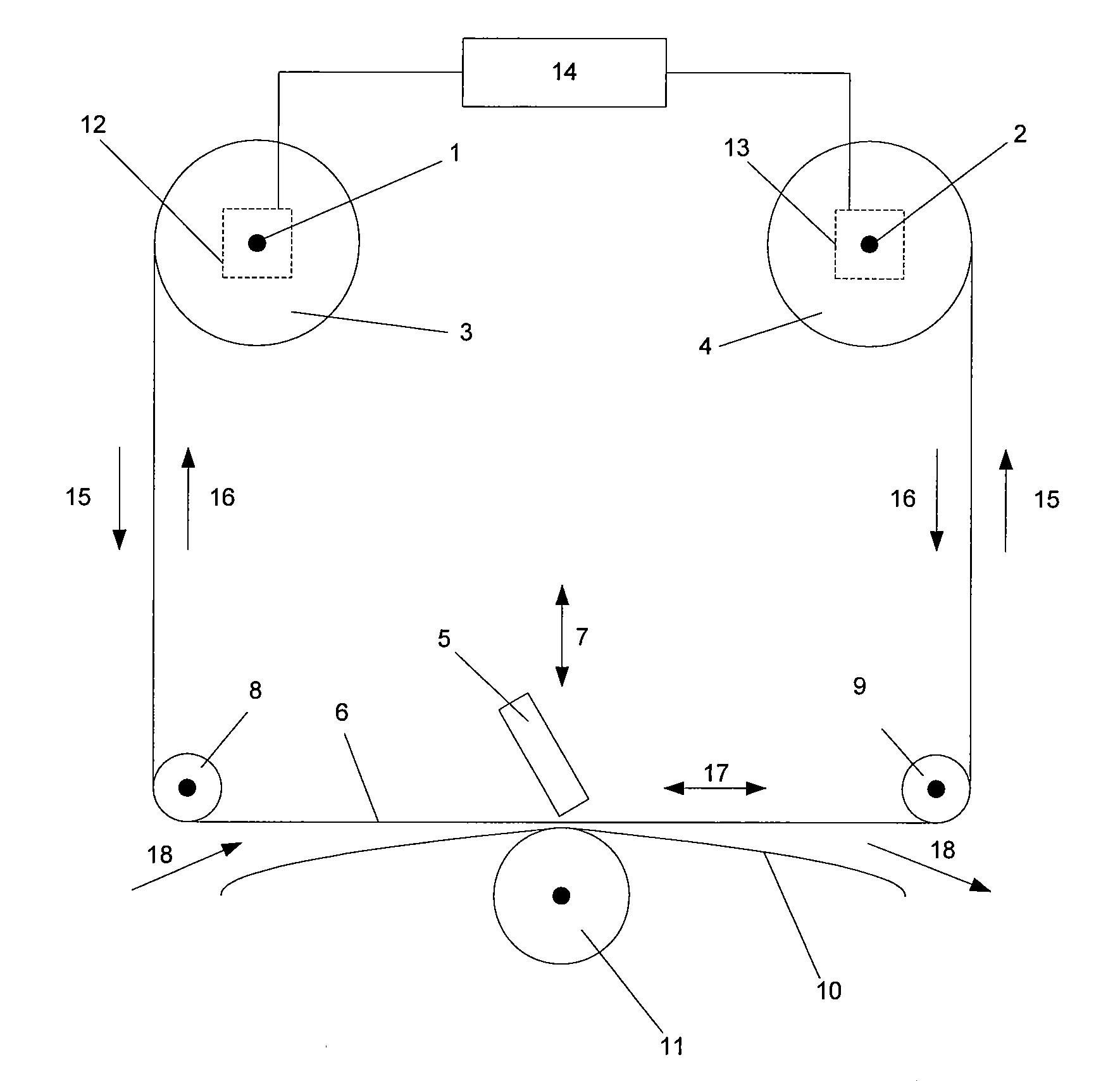
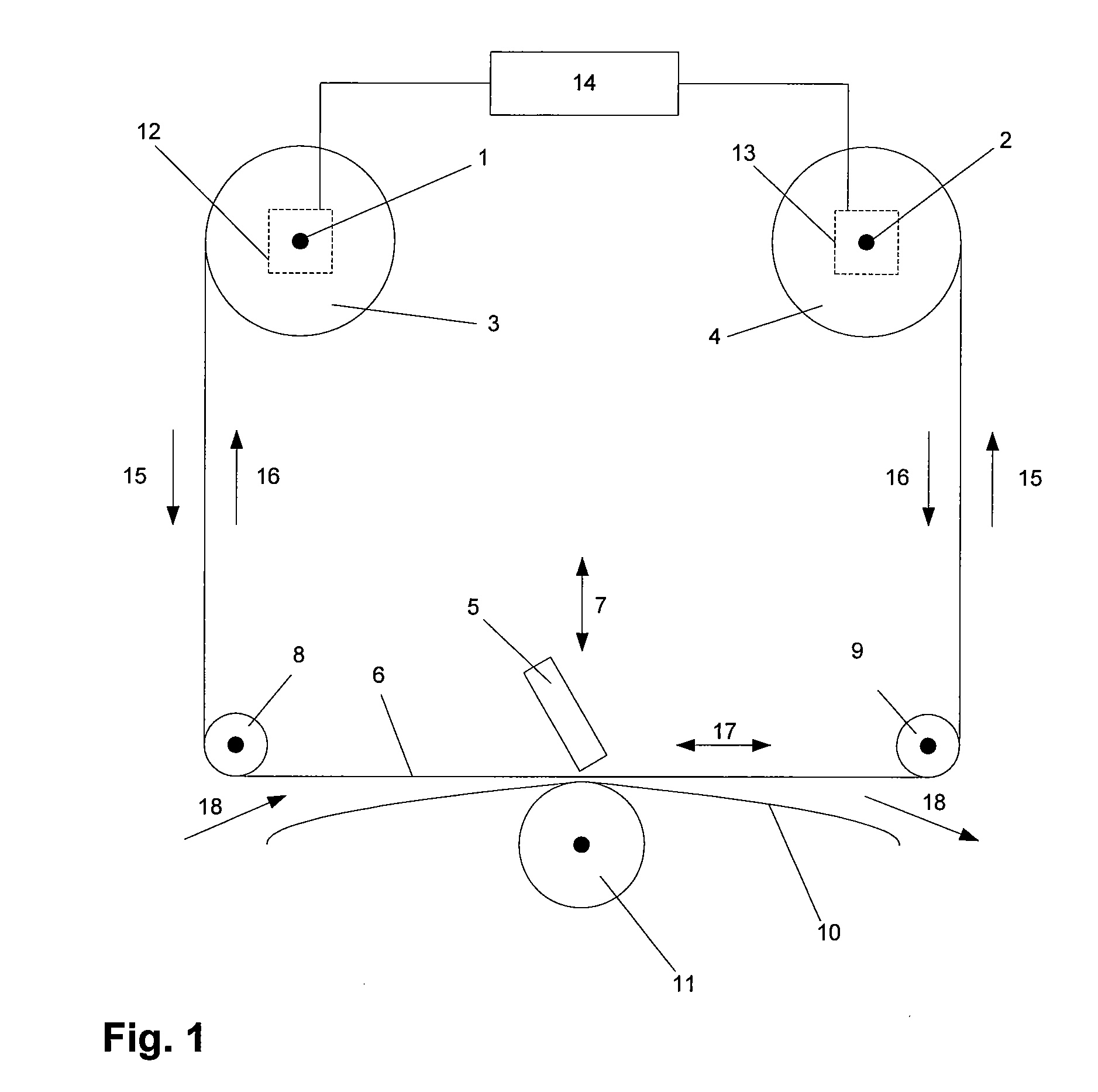
[0038]Referring to FIG. 1, this schematically illustrates a tape drive suitable for use in a thermal transfer printer in accordance with the present invention. First and second shafts 1, 2 support a supply spool 3 and a take-up spool 4 respectively. The supply spool 3 is initially wound with a roll of unused tape, and the take-up spool 4 initially does not carry any tape. As tape is used within a printing operation, used portions of the tape are transported from the supply spool 3 to the take-up spool 4. A displaceable printhead 5 is provided, displaceable relative to tape 6 in at least a first direction indicated by arrow 7. Tape 6 extends from the supply spool 3 around rollers 8, 9 to the take-up spool 4. The path followed by the tape 6 between the rollers 8 and 9 passes in front of the printhead 5. A substrate 10 upon which print is to be deposited is brought into contact with the tape 6 between rollers 8 and 9, the tape 6 being interposed between the printhead 5 and the substrat...
PUM
 Abstract
Description
Claims
Application Information