Diagnosis device for internal combustion engine, and diagnosis method for internal combustion engine

a diagnostic device and internal combustion engine technology, applied in the direction of machines/engines, automatic initiation, electric control, etc., can solve the problems of reducing the opportunity for egr and the inability to complete so as to reduce the possibility of air flow meter diagnosis processing to be executed

Inactive Publication Date: 2017-12-26
TOYOTA JIDOSHA KK
View PDF12 Cites 1 Cited by
  • Summary
  • Abstract
  • Description
  • Claims
  • Application Information

AI Technical Summary

Benefits of technology

[0009]The present invention provides a diagnosis device for an internal combustion engine that can prevent a decrease in reliability of the EGR diagnosis processing and ensure opportunities for the EGR diagnosis processing to be executed.
[0011]The above configuration enables the air flow meter diagnosis processing to be started first and the EGR diagnosis processing to be subsequently executed. On the other hand, when predetermined conditions that suggest that the duration of deceleration of the vehicle will be shorter than the diagnosis time that is required to execute the air flow meter diagnosis processing are fulfilled, the EGR diagnosis processing is executed even if the air flow meter diagnosis processing has not been completed. Thus, a situation can be prevented in which the EGR diagnosis processing cannot be executed for a long period of time because the air flow meter diagnosis processing is repeatedly executed despite the fact that it cannot be completed.
[0012]In other words, according to the above configuration, the EGR diagnosis processing is, basically, executed on condition that the air flow meter diagnosis processing has been started or the air flow meter diagnosis processing has been completed. On the other hand, according to the above configuration, when it is predicted that the air flow meter diagnosis processing cannot be completed, the EGR diagnosis processing is executed. It is, therefore, possible to prevent a decrease in reliability of the EGR diagnosis processing and to ensure opportunities for the EGR diagnosis processing to be executed.
[0015]When a gear position with a high transmission gear ratio has been selected in the transmission, the decelerating effect of the engine brake is stronger and the deceleration of the vehicle tends to be higher compared to when a gear position with a low transmission gear ratio has been selected. Thus, it can be predicted that the duration of deceleration of the vehicle will be shorter as a gear position with a higher transmission gear ratio has been selected in the transmission. In the above diagnosis device, the electronic control unit may be configured to set the determination value to a higher value as a gear position with a higher transmission gear ratio is selected in a transmission of the vehicle. According to the above configuration, the determination value can be determined to a value suitable for the running conditions of the vehicle at the time of determination.
[0016]In the above diagnosis device, the electronic control unit may be configured to execute the air flow meter diagnosis processing without executing the EGR diagnosis processing when the vehicle is decelerated with the predetermined conditions being fulfilled after diagnosis of the EGR device by the EGR diagnosis processing has been completed. According to the above configuration, after the diagnosis of the EGR device by the EGR diagnosis processing has been completed, the air flow meter diagnosis processing is executed even when the vehicle is decelerated with the predetermined conditions being fulfilled. Thus, a situation can be prevented in which the EGR diagnosis processing is repeated despite the fact that the diagnosis of the EGR device by the EGR diagnosis processing has been completed and the opportunities for the air flow meter diagnosis processing to be executed are decreased. Thus, both the diagnosis processing can be completed promptly.

Problems solved by technology

When the diagnosis time that is required to execute the air flow meter diagnosis processing is relatively long, the air flow meter diagnosis processing may not be able to be completed because the deceleration of the vehicle may be ended before the air flow meter diagnosis processing is completed.
In other words, when vehicle deceleration that continues for a short period of time is repeated, the air flow meter diagnosis processing is repeated because the air flow meter diagnosis processing cannot be completed even if it is started, resulting in a decrease of opportunities for EGR diagnosis processing to be executed.

Method used


Image

  • Diagnosis device for internal combustion engine, and diagnosis method for internal combustion engine
  • Diagnosis device for internal combustion engine, and diagnosis method for internal combustion engine
  • Diagnosis device for internal combustion engine, and diagnosis method for internal combustion engine

Examples


Embodiment Construction

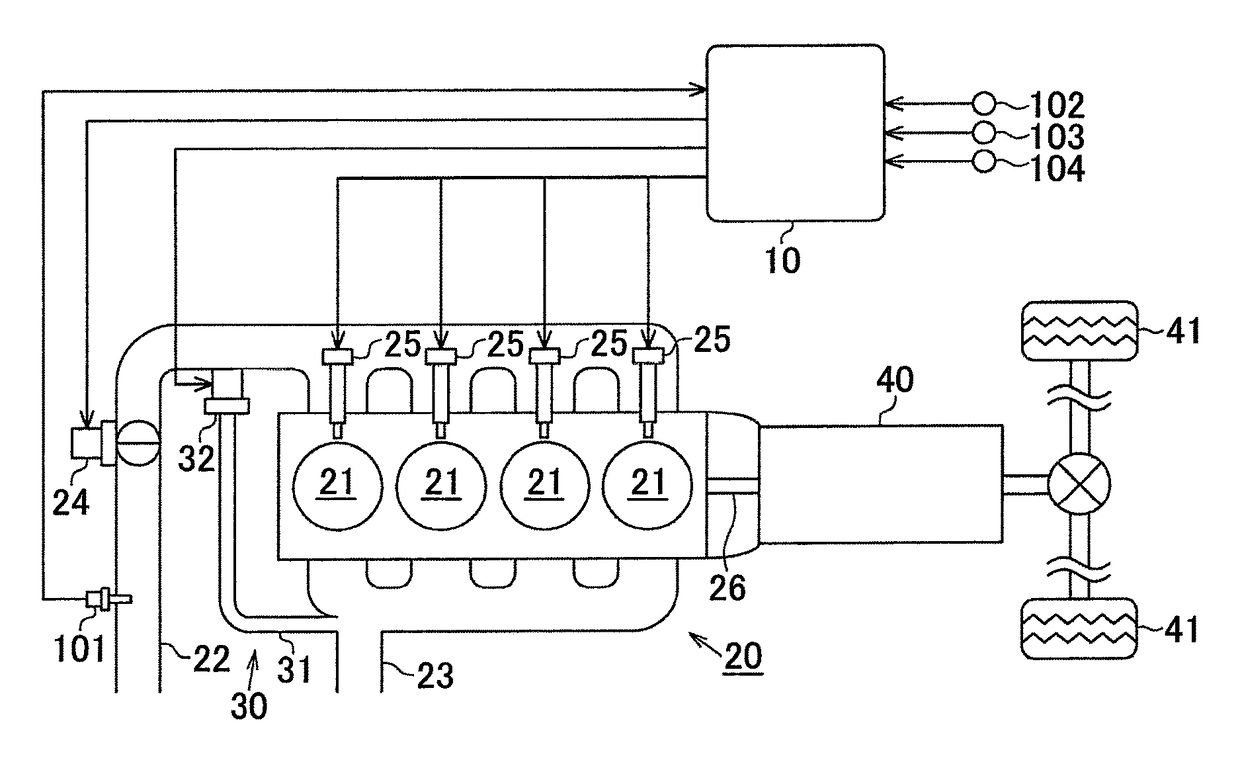
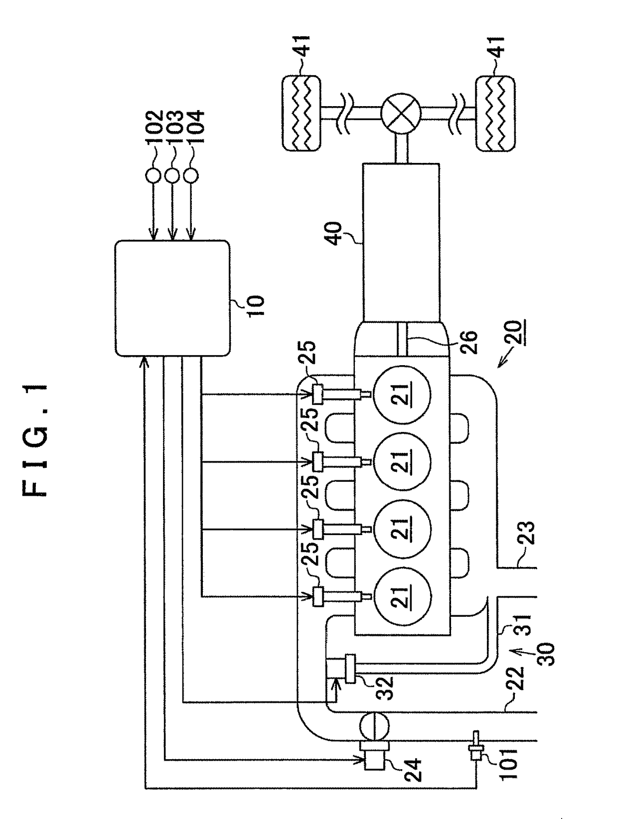
[0025]Description is hereinafter made of one embodiment that embodies a diagnosis device for an internal combustion engine with reference to FIG. 1 to FIG. 6. In FIG. 1, an electronic control unit 10 as a diagnosis device for an internal combustion engine according to this embodiment and an internal combustion engine 20 that is controlled by the electronic control unit 10 are shown. As shown in FIG. 1, the internal combustion engine 20 has an intake pipe 22 that is used to introduce intake air into combustion chambers 21, and an exhaust pipe 23 that is used to discharge exhaust gas that is generated in the combustion chambers 21. The intake pipe 22 is equipped with an air flow meter 101 that detects the intake air amount, i.e., the amount of intake air that is flowing through the intake pipe 22, and a throttle valve 24 that is located downstream of the air flow meter 101 in the direction of intake air flow and adjusts the intake air amount. The intake pipe 22 has intake ports for re...


PUM


Abstract

A diagnosis device for an engine, the diagnosis device includes an electronic control unit. The electronic control unit is configured to execute EGR diagnosis processing to diagnose whether or not the EGR device operates normally while a vehicle is being decelerated, execute air flow meter diagnosis processing to diagnose whether or not the air flow meter is normal while the vehicle is decelerated, execute the EGR diagnosis processing after starting the air flow meter diagnosis processing, and execute the EGR diagnosis processing when the air flow meter diagnosis processing has not been completed and predetermined conditions that a duration of deceleration of the vehicle being shorter than a diagnosis time that is required to execute the air flow meter diagnosis processing are fulfilled.

Description

CROSS-REFERENCE TO RELATED APPLICATIONS[0001]This application is a national phase application of International Application No. PCT / IB2014 / 002585, filed Nov. 14, 2014, and claims the priority of Japanese Application No. 2013-238098, filed Nov. 18, 2013, the content of both of which is incorporated herein by reference.BACKGROUND OF THE INVENTION[0002]1. Field of the Invention[0003]The present invention relates to a diagnosis device for an internal combustion engine and a diagnosis method thereof.[0004]2. Description of Related Art[0005]As disclosed in Japanese Patent Application Publication No. 2005-61335 (JP 2005-61335 A), air flow meter diagnosis processing may be executed when the vehicle is being decelerated with fuel cut off. In the air flow meter diagnosis processing, when the intake air amount that is detected by an air flow meter is out of a predetermined normal range, the duration of the state is measured. When the duration is longer than a threshold value, the air flow meter...

Claims


Application Information

Patent Timeline
Patent Type & Authority Patents(United States)
IPC IPC(8): B60T7/12F02D41/24F02D41/18F02D41/22F02M26/49F02D41/00F02D41/02F02D41/12
CPCF02D41/005F02D41/0005F02D41/18F02D41/222F02D41/24F02M26/49Y02T10/42F02D41/0072F02D41/0225F02D41/12F02D2200/0402F02D2200/0406Y02T10/40
Inventor MIYAHARA, HIDEKIKAWASE, KENICHIRO
Owner TOYOTA JIDOSHA KK
Why Eureka
Try Eureka