
Braking control device for vehicle

a technology for controlling devices and vehicles, applied in brake action initiation, brake systems, transportation and packaging, etc., can solve the problems of not meeting the current demand for operator response, affecting the operability of the operator and the response of the vehicle,

Active Publication Date: 2019-12-10
MAZDA MOTOR CORP
View PDF25 Cites 0 Cited by
  • Summary
  • Abstract
  • Description
  • Claims
  • Application Information

AI Technical Summary

Benefits of technology

[0008]Therefore, one purpose of the present disclosure is to provide a braking control device which is capable of achieving both operability by a vehicle operator and a response of the vehicle at any operating states.
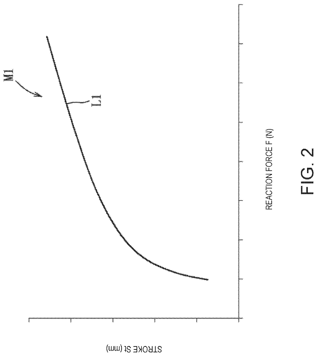
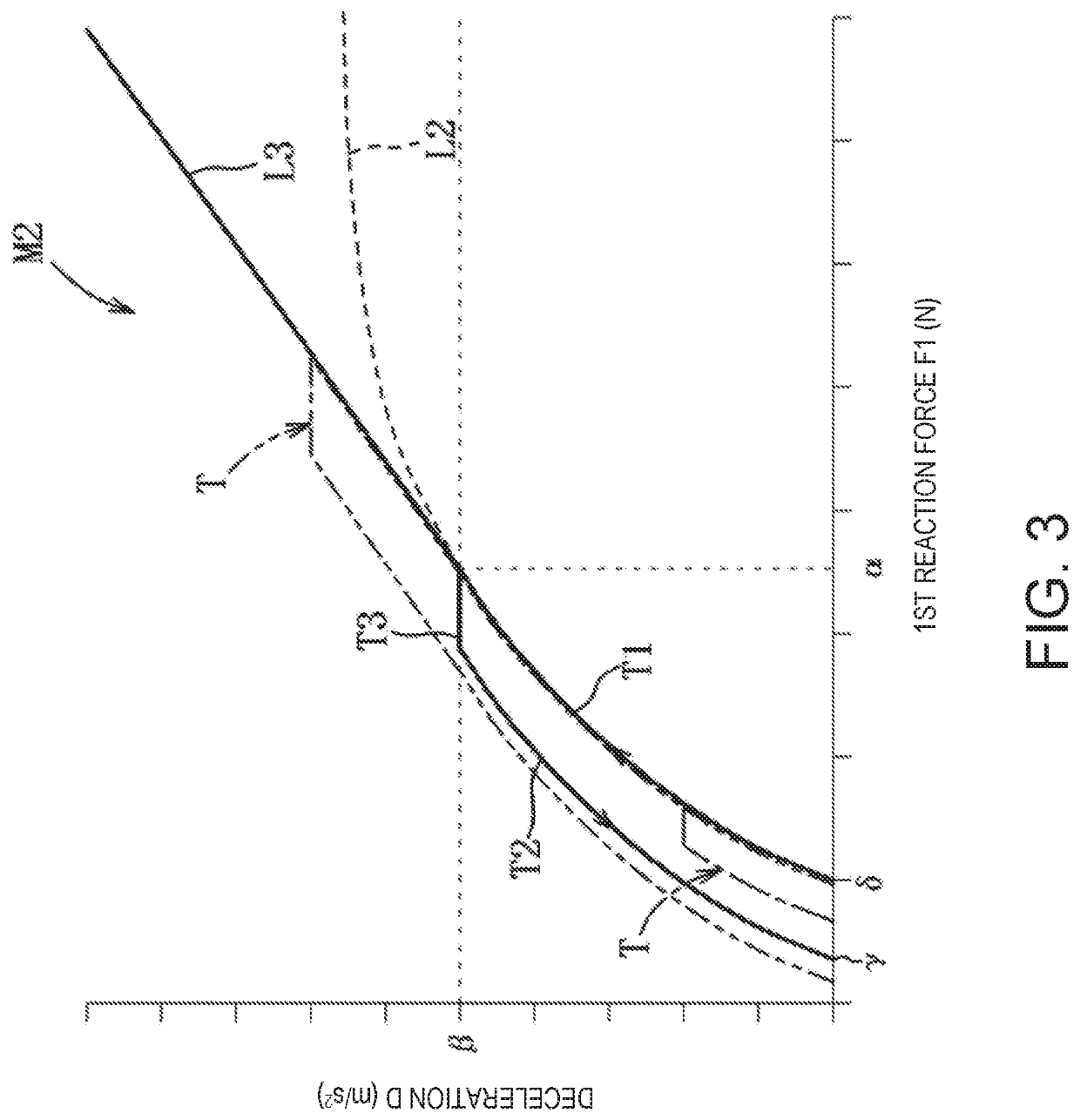
[0010]Since this braking control device includes the braking characteristic setting module configured to set the braking characteristic in which the reaction force according to the stepping force of the brake pedal and the deceleration of the vehicle have a logarithmic relationship, the deceleration proportional to the reaction force can be perceived by a vehicle operator, thereby improving operability of the brake pedal. When above the given reaction force, since the controller makes the deceleration for the reaction force higher than the logarithmic relationship and controls the braking-force generating part based on the braking characteristic, the deceleration can be controlled so as to be increased more than the linear relationship between a perceived operating amount of the operator according to the reaction force and a behavior of the vehicle at emergency braking where the reaction force becomes above the given reaction force, thereby demonstrating a braking performance with high response corresponding to a sudden slowdown intention of the operator.
[0011]When the reaction force is more than the given reaction force, the control module may control the braking-force generating part so that the deceleration becomes proportional to the reaction force. According to this configuration, the operator's perceived deceleration is increased while simplifying the configuration, thereby improving the operability at the emergency braking.
[0012]The braking characteristic setting module may set a stepping characteristic that is a correlation between a deceleration of the vehicle and a reaction-force giving value from a start to an end of stepping on the brake pedal, and a releasing characteristic that is a correlation between a deceleration of the vehicle and a reaction-force giving value from a start to an end of releasing the brake pedal, and the releasing characteristic is obtained by offsetting the stepping characteristic to a decreasing side of the reaction-force giving value. According to this configuration, a change tendency of the releasing characteristic and a change tendency of the stepping characteristic can be made substantially similar to each other, and the generation of the odd feel can be avoided when the operator shifts from the stepping operation to the releasing operation.

Problems solved by technology

However, even if such a braking characteristic is set so that the reaction force of the brake pedal and the deceleration of the vehicle have the logarithmic relationship, there is still a possibility that the operator's intention does not match with the vehicle behavior.
On the other hand, when emergency braking is caused, for example, by a sudden appearance of an obstacle, since the operator's intention is independent of their consciousness before this moment and a higher braking characteristic is demanded, the previous braking characteristic may not meet the response currently demanded by the operator.
That is, it is not easy to achieve both the operability by the operator and the response of the vehicle at any operating state.

Method used


Image

  • Braking control device for vehicle
  • Braking control device for vehicle
  • Braking control device for vehicle

Examples


Embodiment Construction

[0019]Hereinafter, one embodiment of the present disclosure is described in detail based on the accompanying drawings. The following description merely illustrates the present disclosure being applied to a braking control device for a vehicle, and thus, this description is not to limit the present disclosure, its applications, or its use.

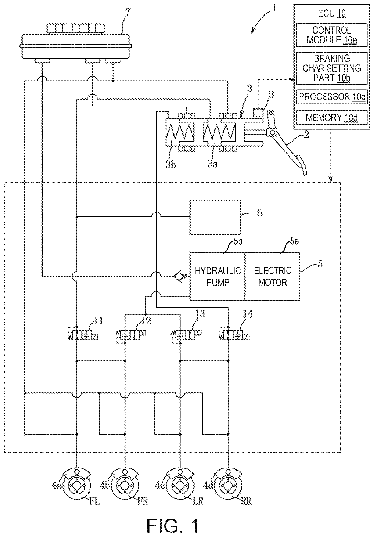
[0020]Below, one embodiment of the present disclosure is described based on FIGS. 1 to 5. As illustrated in FIG. 1, a braking control device 1 constitutes a brake-by-wire mechanism, and includes a master cylinder 3 capable of generating brake hydraulic pressure corresponding to a stroke (stepping state) of a brake pedal 2, and a braking hydraulic pressure generating mechanism 5 (braking-force generating part) capable of supplying brake hydraulic pressure to wheel cylinders 4a-4d which respectively brake the rotations of front and rear, and left and right wheels FL, FR, RL, and RR of a vehicle. The device 1 is configured so that, when the braking hyd...


PUM


Abstract

A braking control device for a vehicle is provided, which includes an operating amount detecting part configured to detect an operating amount of a brake pedal, a reaction-force giving part configured to generate a reaction force of the brake pedal, a braking-force generating part configured to generate a braking force for wheels, and an ECU electrically connected with them and configured to control the reaction-force giving part and the braking-force generating part, and set a braking characteristic in which the reaction force according to a stepping force of the brake pedal and a deceleration of the vehicle have a logarithmic relationship, and when the reaction force is above a given reaction force. The ECU controls the braking-force generating part based on the braking characteristic while making the deceleration for the reaction force higher than the logarithmic relationship.

Description

TECHNICAL FIELD[0001]The present disclosure relates to a braking control device for a vehicle, and particularly to the braking control device capable of controlling behavior of the vehicle based on a braking characteristic which conforms to a human perception characteristic.BACKGROUND OF THE DISCLOSURE[0002]Conventionally, in a vehicle control, when a vehicle operator operates a brake pedal, a target operating amount is set based on an operating characteristic (control map) where a correlation between an operating amount of the brake pedal and a deceleration of the vehicle is defined, and the behavior of the vehicle is controlled based on the target operating amount. Meanwhile, in order to improve an operating feel of the operator, numerous controllers which perform a vehicle control conforming to the operator's sensitivity based on psychophysics are proposed. As expressions of a relationship between the physical quantity and the sensation (perceived intensity) in the form of a func...

Claims


Application Information

Patent Timeline
Patent Type & Authority Patents(United States)
IPC IPC(8): B60T8/1755B60T8/171B60T7/04B60T7/06B60T8/40B60T13/68B60T8/172B60T13/66B60T8/32
CPCB60T13/662B60T8/17555B60T7/042B60T8/172B60T8/171B60T2220/04B60T7/06B60T8/326B60T8/4072B60T13/686B60T2220/02B60T8/4081B60T8/409B60T2270/82
Inventor TAKEMURA, KAZUHIROYAMADA, NAOKITANGO, YUTAKAIHARA, SHINICHIKYUTO, NOBORUMOCHIZUKI, HIROTAKAKAMURA, TAKANOBU
Owner MAZDA MOTOR CORP
Learn More