Power transmission apparatus

a technology of transmission apparatus and motor, which is applied in the direction of bridges, machines, and ways, can solve the problems of damage to the motor, difficulty in obtaining high torque levels, and degree of deceleration, and achieve high torque and high deceleration

Inactive Publication Date: 2008-07-10
SAMSUNG ELECTRO MECHANICS CO LTD
View PDF8 Cites 0 Cited by
  • Summary
  • Abstract
  • Description
  • Claims
  • Application Information

AI Technical Summary

Benefits of technology

[0009]An aspect of the invention is to provide a power transmission apparatus, which can provide high deceleration and high torque, even when a low-capacity motor having a low cogging torque is used.

Problems solved by technology

Thus, as the high rotational speed of the motor has to be reduced to several to several tens of revolutions per minute, a sufficient degree of deceleration may not be achieved with only a gear module, and it may be difficult to obtain high levels of torque.
Furthermore, if the television or computer monitor is rotated, not by the electrical driving of the motor, but by an external force from the user, an excessive load may be imposed on the motor connected to the rotational axis, causing damage to the motor.
In addition, when a mass rotated automatically using a motor having a gear module is stopped from rotating, there is a risk of the mass shaking, due to the backlash between gears within the gear module and other tolerances in each assembly part.

Method used


Image

  • Power transmission apparatus
  • Power transmission apparatus
  • Power transmission apparatus

Examples


Embodiment Construction

[0023]The power transmission apparatus according to certain embodiments of the invention will be described below in more detail with reference to the accompanying drawings, in which those components are rendered the same reference numeral that are the same or are in correspondence, regardless of the figure number, and redundant explanations are omitted.

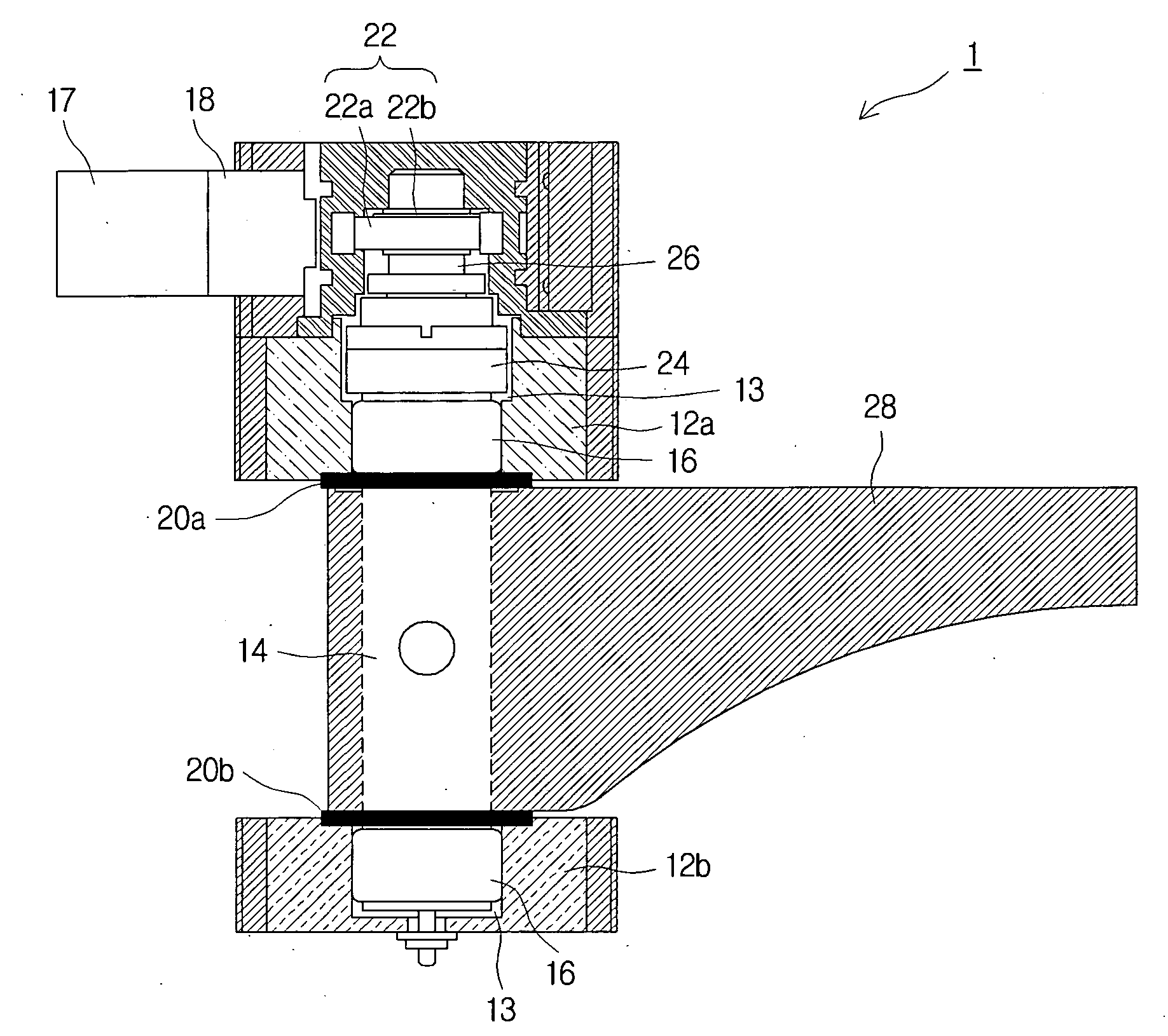
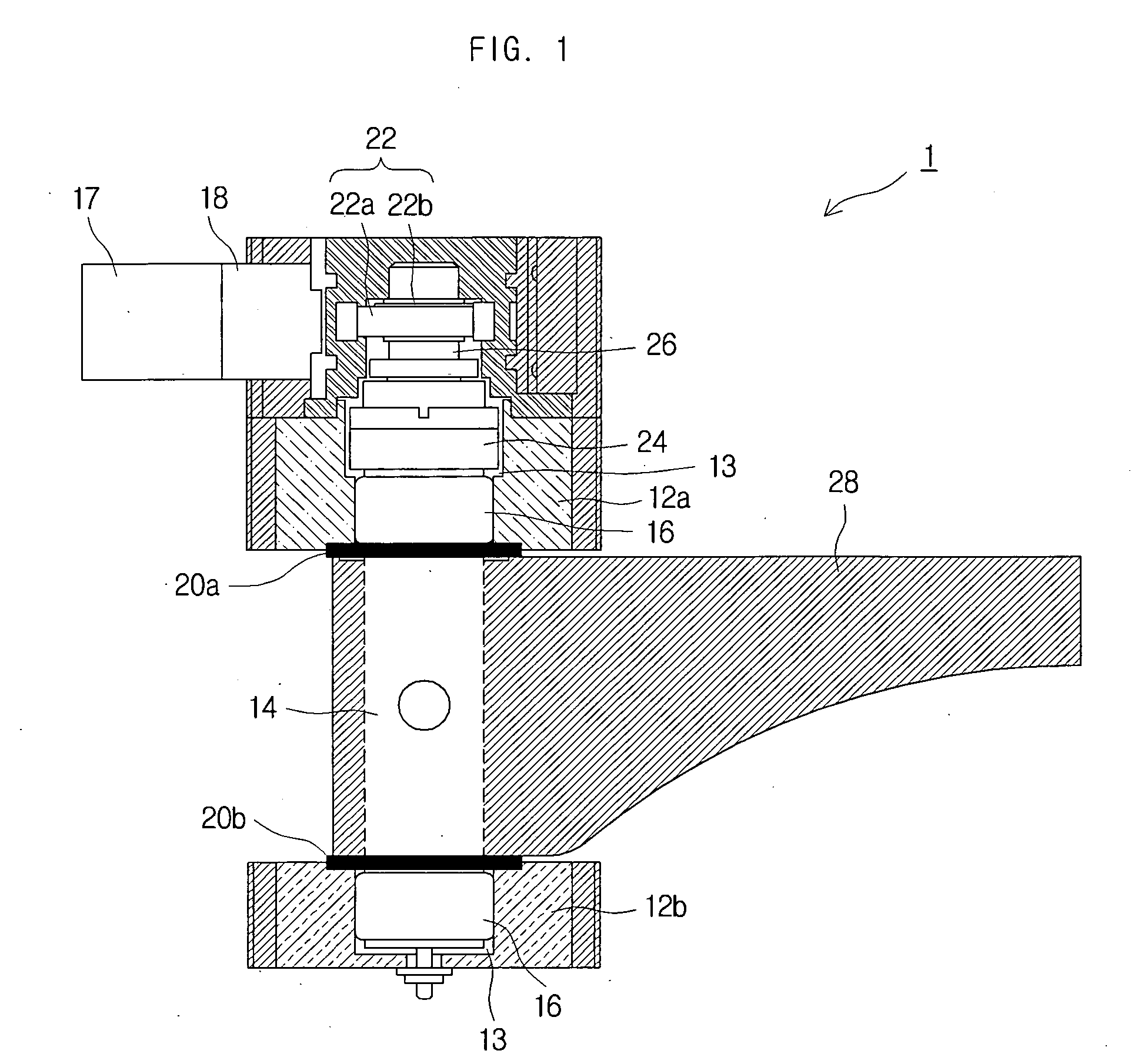
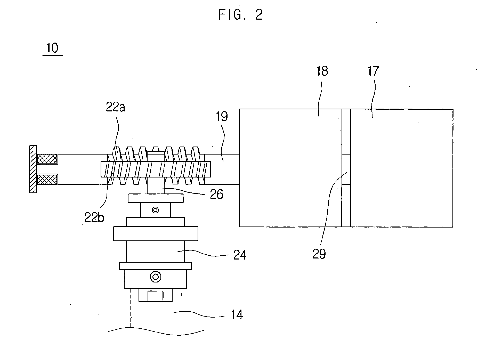
[0024]FIG. 1 is a cross-sectional view of a power transmission apparatus according to an embodiment of the present invention, and FIG. 2 is a cross-sectional view of a power generation part according to an embodiment of the present invention. In FIG. 1, and FIG. 2, there are illustrated a power transmission apparatus 1, a power generation part 10, brackets 12a, 12b, hinge cavities 13, a hinge axis 14, friction bearings 16, a gear module 18, a main axis 19, washers 20a, 20b, a worm gear module 22, a worm 22a, a worm gear 22b, a friction hinge 24, an output axis 26, a link member 28, and a drive axis 29.

[0025]The brackets 12a, 12b may r...


PUM


Abstract

A power transmission apparatus is disclosed. A power transmission apparatus that includes: a bracket, in which a hinge cavity is formed; a hinge axis, which is rotatably joined to the hinge cavity; a friction bearing, which is positioned between the hinge axis and an inner wall of the hinge cavity, and which is configured to provide a predetermined friction; and a gear module, which is joined to the hinge axis, and which is configured to provide a rotational force to the hinge axis, can provide sufficiently high deceleration and high torque, even when a low-capacity motor having a low cogging torque is used. Also, the power transmission apparatus can be made safer and less noisy for not only automatic operation by the motor but also manual operation by a user, while the gear module, motor, etc., can be protected from excessive loads.

Description

CROSS-REFERENCE TO RELATED APPLICATIONS[0001]This application claims the benefit of Korean Patent Application No. 10-2007-0001987 filed with the Korean Intellectual Property Office on Jan. 8, 2007, the disclosure of which is incorporated herein by reference in its entirety.BACKGROUND[0002]1. Technical Field[0003]The present invention relates to a power transmission apparatus.[0004]2. Description of the Related Art[0005]A gear module joined to a motor may serve to reduce the rotational speed transferred from the motor by a particular rate. Multiple gears can be arranged in a gear module, with the rotation of the motor decelerated by the combination of these gears.[0006]Rotating a mass such as a television or computer monitor, however, requires high torque, although a high rotational speed may not be necessary. Thus, as the high rotational speed of the motor has to be reduced to several to several tens of revolutions per minute, a sufficient degree of deceleration may not be achieved ...

Claims


Application Information

Patent Timeline
Patent Type & Authority Applications(United States)
IPC IPC(8): E05D11/08
CPCF16M11/08F16M11/18Y10T16/54033F16M13/02F16M11/2014E01C9/08E01C9/083E01D19/125
Inventor CHOI, DONG-WONLEE, CHIL-SUNGKIM, JAE-KYUNGKIM, JAE-HUNPARK, KYOUNG-SHIN
Owner SAMSUNG ELECTRO MECHANICS CO LTD
Why Eureka
Try Eureka