Brake system and method for operating a brake system

a brake system and brake pedal technology, applied in the direction of brake systems, vehicle sub-unit features, transportation and packaging, etc., can solve the problems of a greatly extended brake pedal travel, particularly for heavy vehicles with large wheels, and achieve the effect of higher braking deceleration

Active Publication Date: 2022-03-15
CONTINENTAL TEVES AG & CO OHG
View PDF16 Cites 1 Cited by
  • Summary
  • Abstract
  • Description
  • Claims
  • Application Information

AI Technical Summary

Benefits of technology

[0012]The embodiments offer the advantage of full exploitation of the deceleration potential at the rear axle without using the energy of the driver's foot. The energy of the driver's foot is concentrated on the braking effect at the front axle and thus a higher deceleration is achieved overall.
[0013]The hydraulic service brake device is embodied in such a way that the master brake cylinder is connected exclusively to the hydraulically actuatable first wheel brakes at the front wheels in the deenergized state of the hydraulic service brake device.
[0014]Alternatively, the hydraulic service brake device is embodied in such a way that the master brake cylinder is connected to the hydraulically actuatable first wheel brakes at the front wheels and to the hydraulically actuatable second wheel brakes at the rear wheels in the deenergized state of the hydraulic service brake device.
[0015]The electronic open-loop and closed-loop control unit comprises at least one first electric and / or electronic means for controlling the electrically actuatable components of the hydraulic service brake device and at least one second electric and / or electronic means, embodied separately from the first means, for controlling the electric-motor-actuatable wheel brakes. In the event of a failure of the first means for controlling the hydraulic service brake device, the rear wheels can thus nevertheless be braked by means of the electric-motor-actuatable wheel brakes in the hydraulic fallback operating mode. This increases the availability for braking with a high deceleration.
[0016]Signals from wheel speed sensors arranged at the front and rear wheels are preferably fed to the second means. The necessary data for wheel slip control at the rear wheels by means of the parking brake device are thus available in the second means.
[0017]The second electric and / or electronic means is preferably designed for carrying out wheel slip control at the rear wheels by means of the electric-motor-actuatable wheel brakes. Thus, wheel slip control can be carried out at the rear wheels by the electric-motor-actuatable wheel brakes by means of the second means, even in the event of failure of the first means.
[0018]The wheel speed sensor signals are preferably transferred from the second means to the first means.
[0021]The second means is additionally designed to control the inlet valves of the second wheel brakes. This is advantageous particularly in the case of a hydraulic service brake device in which the master brake cylinder is connected to the hydraulically actuatable first and second wheel brakes in the deenergized state of the hydraulic service brake device. It is thus possible, in the deenergized state of the hydraulic service brake device, for the inlet valves of the second wheel brakes to be closed by means of the second means so that the second wheel brakes are not connected to the master brake cylinder in the hydraulic fallback operating mode.
[0022]A method for operating a “brake-by-wire” brake system having a hydraulic service brake device for front and rear wheels and a parking brake device having electric-motor-actuatable wheel brakes at the rear wheels. Here, in a hydraulic fallback operating mode of the brake system, in the case of a brake pedal actuation by a vehicle driver, only the hydraulic front wheel brakes are connected to the master brake cylinder and are supplied with pressure by the driver by means of the master brake cylinder, while the rear wheels are braked exclusively by means of the electric-motor-actuatable wheel brakes.
[0023]In one or more embodiments, if, in the hydraulic fallback operating mode, the inlet valves of the hydraulic rear wheel brakes are closed, with the result that only the hydraulic front wheel brakes are connected to the master brake cylinder and are supplied with pressure by the vehicle driver by means of the master brake cylinder. In the hydraulic fallback operating mode, wheel slip control is preferably carried out at the rear wheels by means of the electric-motor-actuatable wheel brakes.
[0022]A method for operating a “brake-by-wire” brake system having a hydraulic service brake device for front and rear wheels and a parking brake device having electric-motor-actuatable wheel brakes at the rear wheels. Here, in a hydraulic fallback operating mode of the brake system, in the case of a brake pedal actuation by a vehicle driver, only the hydraulic front wheel brakes are connected to the master brake cylinder and are supplied with pressure by the driver by means of the master brake cylinder, while the rear wheels are braked exclusively by means of the electric-motor-actuatable wheel brakes.
[0024]The brake system preferably comprises an electrically actuatable, advantageously normally closed, simulator valve by means of which the effect of the simulation device can be activated and deactivated. As a particular preference, the simulator valve is arranged between the master brake cylinder and the simulation device.

Problems solved by technology

Heavy vehicles (e.g. SUVs) with large wheels are at a particular disadvantage.
Although this has the effect of a relatively high pressure, there is the disadvantage of a greatly extended brake pedal travel.

Method used


Image

  • Brake system and method for operating a brake system
  • Brake system and method for operating a brake system
  • Brake system and method for operating a brake system

Examples


Embodiment Construction

[0010]The following detailed description includes references to the accompanying drawings, which form a part of the detailed description. The drawings show, by way of illustration, specific embodiments in which the apparatus may be practiced. These embodiments, which are also referred to herein as “examples” or “options,” are described in enough detail to enable those skilled in the art to practice the present embodiments. The embodiments may be combined, other embodiments may be utilized, or structural or logical changes may be made without departing from the scope of the invention. The following detailed description is, therefore, not to be taken in a limiting sense and the scope of the invention is defined by the appended claims and their legal equivalents.

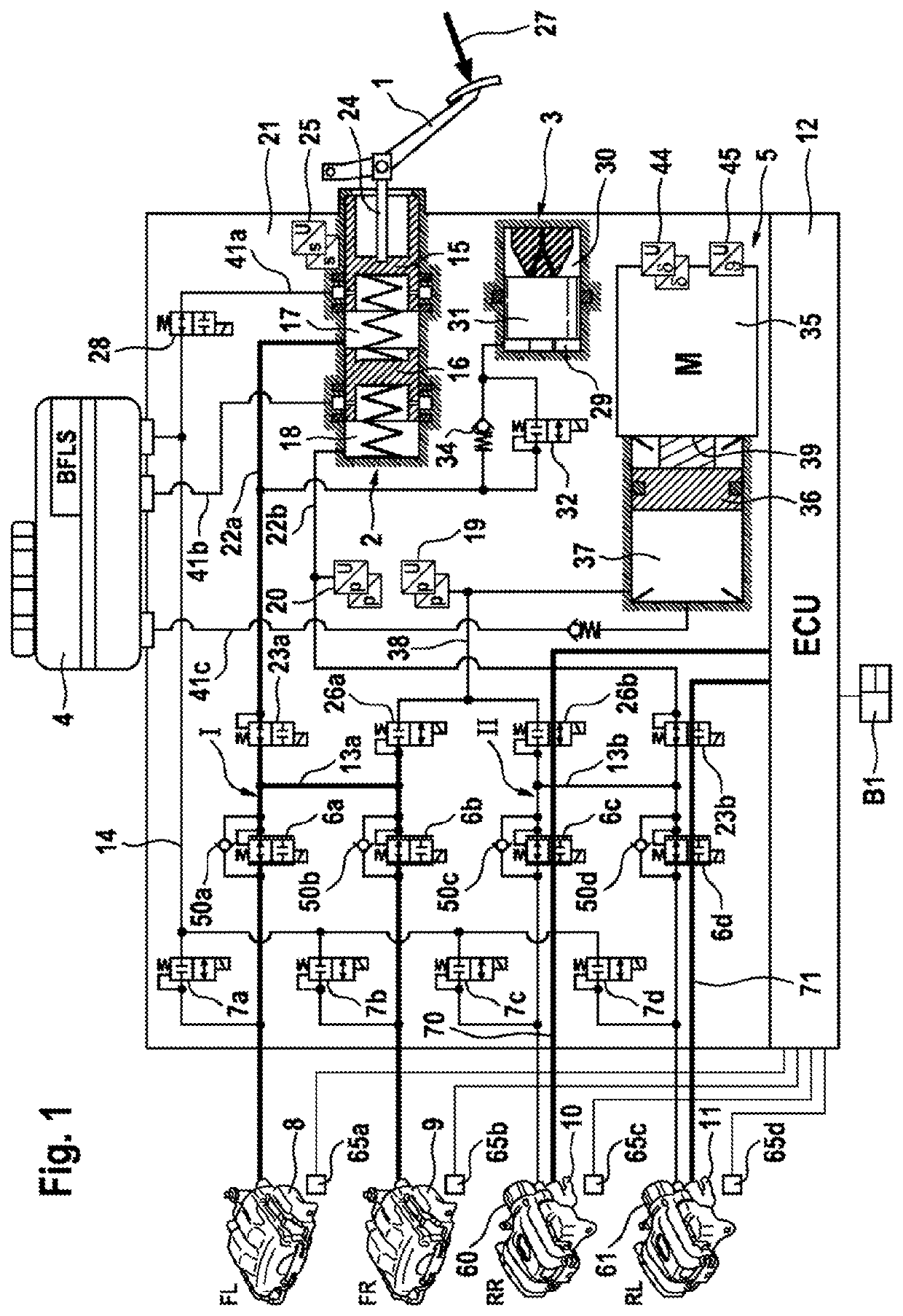
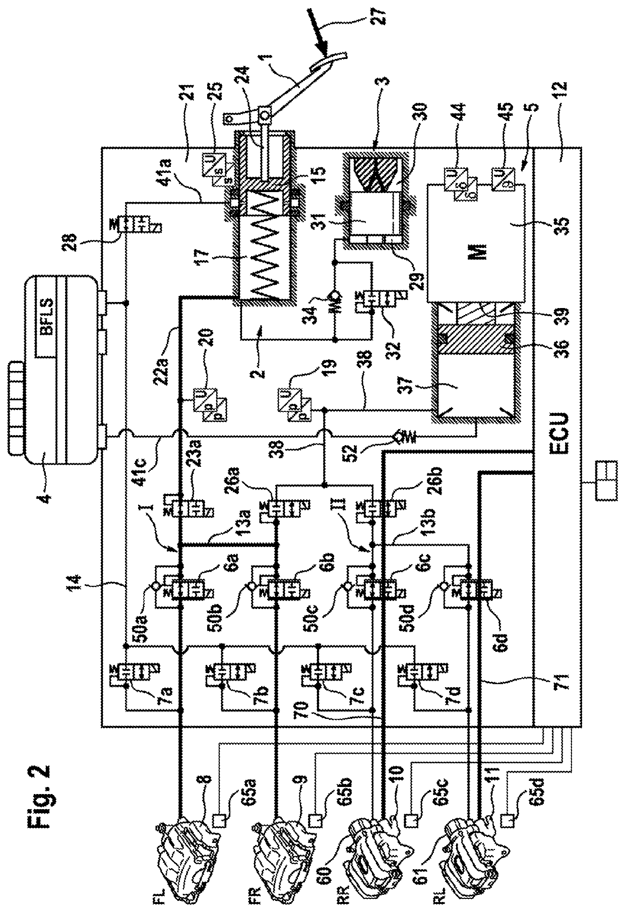
[0011]In a hydraulic fallback operating mode of the brake system, in the case of a brake pedal actuation by a vehicle driver, only the hydraulically actuatable wheel brakes at the front wheels are connected to the master brake ...


PUM


Abstract

Brake system of a motor vehicle having front wheels and rear wheels having a hydraulic service brake device. The system further includes an electrically actuatable pressure-providing device, wherein the pressure-providing device is connected to the first and second wheel brakes, comprising a parking brake device having electric-motor-actuatable wheel brakes at the rear wheels, and an electronic open-loop and closed-loop control unit, wherein in a hydraulic fallback operating mode of the brake system, in the case of a brake pedal actuation by a vehicle driver, only the first wheel brakes are connected to the master brake cylinder and supplied with pressure by the driver by the master brake cylinder, while the rear wheels are braked by the electric-motor-actuatable wheel brakes.

Description

CROSS REFERENCE TO RELATED APPLICATIONS[0001]This application is the U.S. national phase application of PCT International Application No. PCT / EP2018 / 060397, filed Apr. 24, 2018, which claims priority to German Patent Application No. DE 10 2017 208 178.3, filed May 16, 2017, wherein the contents of such applications are incorporated herein by reference.TECHNICAL FIELD[0002]A brake system and method for operating a brake system.TECHNICAL BACKGROUND[0003]DE 10 2013 224 870 A1 relates to a “brake-by-wire” brake assembly for motor vehicles which comprises a tandem master brake cylinder which can be actuated by means of a brake pedal and the two pressure spaces of which are in each case connected, separably by means of an electrically actuatable isolating valve, to a brake circuit with two wheel brakes, an activatable and deactivatable simulation device which is hydraulically connected to the master brake cylinder, and an electrically controllable pressure-providing device which is formed...

Claims


Application Information

Patent Timeline
Patent Type & Authority Patents(United States)
IPC IPC(8): B60T13/74B60T8/40B60T13/68B60T7/04B60T13/66
CPCB60T8/4081B60T13/686B60T7/042B60T13/662B60T13/745B60T2270/82B60Y2400/81B60T8/32B60T8/321B60T8/26B60T8/40B60T13/146B60T8/329B60Y2400/3032
Inventor LINHOFF, PAULBESIER, MARCODRUMM, STEFANHEISE, ANDREAS
Owner CONTINENTAL TEVES AG & CO OHG
Why Eureka
Try Eureka