Brake system

a technology of brake system and brake plate, which is applied in the direction of brake system, brake components, vehicle components, etc., to achieve the effect of preventing the phenomenon of jackkni

Pending Publication Date: 2022-06-02
TOYOTA JIDOSHA KK
View PDF0 Cites 2 Cited by
  • Summary
  • Abstract
  • Description
  • Claims
  • Application Information

AI Technical Summary

Benefits of technology

[0004]The inventor of the present application has obtained the following findings. In the combination vehicle constituted by a plurality of vehicles for each of which a brake device is provided, optimization of the magnitude, the timing of generation, etc., of the braking force generated by each brake device enables the combination vehicle to enjoy advantages such as prevention of the jackknife phenomenon without fixing the coupler as conventionally performed. Accordingly, an aspect of the present disclosure is directed to a practical brake system for the combination vehicle.
[0012]The brake system according to the present disclosure enables the braking force generated by the brake device installed on each of the plurality of vehicles to be optimized, thus effectively preventing the jackknife phenomenon described above.VARIOUS FORMS
[0030]This form is another form of the present disclosure. This form effectively prevents what is called jackknife phenomenon. The “deceleration adjusting control” in this form includes a control in which the deceleration is determined to be the same for all of the plurality of vehicles. Further, the “braking-force generation-timing adjusting control” in this form includes a control in which the braking force is applied to all of the plurality of vehicles at the same timing. From the viewpoint of preventing the jackknife phenomenon, it is at least desirable that the deceleration of the rearmost vehicle be higher than the deceleration of the foremost vehicle, and it is at least desirable that the timing at which the braking force is applied to the rearmost vehicle is earlier than the timing at which the braking force is applied to the foremost vehicle. It is noted that the braking-force generation-timing adjusting control may also be referred to as a control of adjusting a moment of initiation of braking.
[0033]This form enables the deceleration adjusting control to be appropriately executed even when the loaded weight of each vehicle changes.
[0036]The above two forms prevent the jackknife phenomenon with high reliability.

Problems solved by technology

For instance, the combination vehicle may suffer from a phenomenon in which the combination vehicle is bent at a coupler when braked, namely, the combination vehicle may suffer from what is called jackknife phenomenon when braked.

Method used


Image

  • Brake system
  • Brake system
  • Brake system

Examples


Embodiment Construction

[0052]Referring to the drawings, there will be explained below in detail a brake system according to one embodiment of the present disclosure. It is to be understood that the present disclosure is not limited to the details of the following embodiment but may be embodied based on the forms described in Various Forms and may be changed and modified based on the knowledge of those skilled in the art.

A. Brake System and Overall Structure of Combination Vehicle Equipped with Brake System

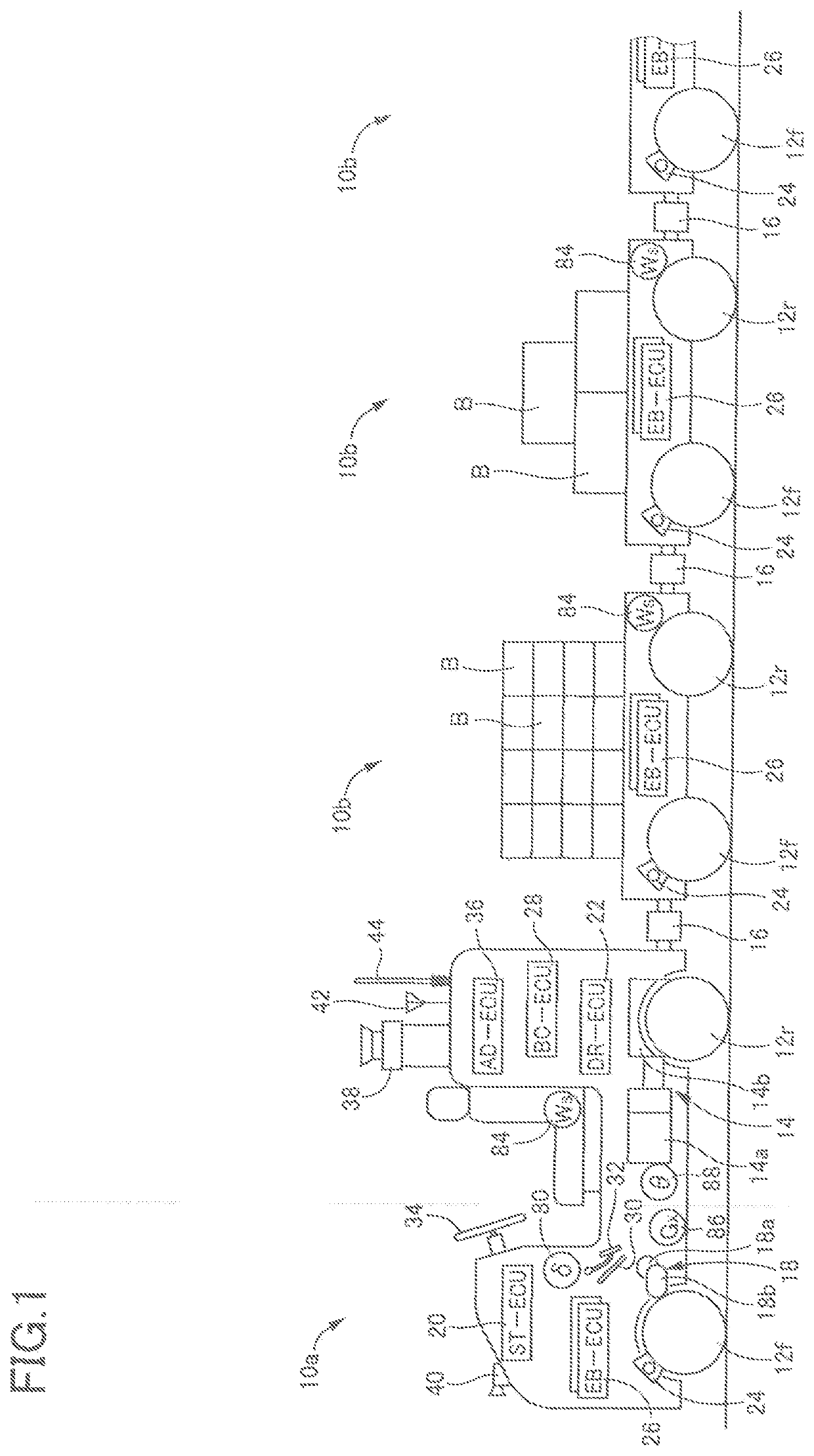
[0053]As schematically illustrated in FIG. 1, the brake system according to the present embodiment is installed on a combination vehicle. The combination vehicle is constituted by a plurality of vehicles that are coupled in a line. The combination vehicle is used for transporting loads as objects in factories, business facilities, etc. The left side in FIG. 1 corresponds to the front side of the combination vehicle. The plurality of vehicles that constitute the combination vehicle includes a tow vehicle ...


PUM


Abstract

A brake system for a combination vehicle in which a plurality of vehicles are coupled in a line, including: a plurality of brake devices respectively provided for the plurality of vehicles; and a controller configured to control the plurality of brake devices, wherein the controller is configured to control a braking force applied to each of the plurality of vehicles based on a loaded weight or a weight of each of the plurality of vehicles.

Description

CROSS REFERENCE TO RELATED APPLICATION[0001]The present application claims priority to Japanese Patent Application No. 2020-196780, which was filed on Nov. 27, 2020, the disclosure of which is herein incorporated by reference in its entirety.BACKGROUNDTechnical Field[0002]The following disclosure relates to a brake system for a combination vehicle constituted by a plurality of vehicles coupled in a line.Description of Related Art[0003]Special consideration is required in braking a combination vehicle constituted by a plurality of vehicles that are coupled in a line. For instance, the combination vehicle may suffer from a phenomenon in which the combination vehicle is bent at a coupler when braked, namely, the combination vehicle may suffer from what is called jackknife phenomenon when braked. In Patent Document 1 (Japanese Patent Application Publication No. 2007-210594), the coupler is fixed to prevent the phenomenon.SUMMARY[0004]The inventor of the present application has obtained ...

Claims


Application Information

Patent Timeline
Patent Type & Authority Applications(United States)
IPC IPC(8): B60T8/1755B60T8/17B60T7/20
CPCB60T8/1755B60T8/1701B60T7/20B60W60/00256B60T2250/00B60T2210/20B60T2250/02B60T8/1708B60T8/18B60T8/28B60T17/228B60T13/662B60T13/665B60T8/323
Inventor TAKASUGA, KAZUKI
Owner TOYOTA JIDOSHA KK
Why Eureka
Try Eureka