Method and apparatus for contactless power transfer

a technology of contactless power transfer and power supply, which is applied in the direction of transformers, inductances, safety/protection circuits, etc., can solve the problems of weak connection between primary and secondary coils, affecting the operation of contactless power systems, and reducing efficiency, so as to reduce unloaded power losses, limit unloaded power losses, and mitigate the effect of such effects

Active Publication Date: 2014-03-18
UNIV OF FLORIDA RES FOUNDATION INC
View PDF7 Cites 255 Cited by
  • Summary
  • Abstract
  • Description
  • Claims
  • Application Information

AI Technical Summary

Benefits of technology

[0018]Embodiments of the impedance transformation network enables the contactless power system to avoid one or more of the four common problems described above, without any feedback, communication, and / or control functionality. The pre-existing power and battery charge management circuitry for a load, which may include a voltage regulator, can regulate the power output of a contactless power system under normal modes of operation. In accordance with embodiments of the invention, contactless power systems can be combined with very simple controls to improve the performance of the system. In this preferred mode of operation, a contactless power system can predictably and reliably deliver power to a load across a wide range of load impedances.
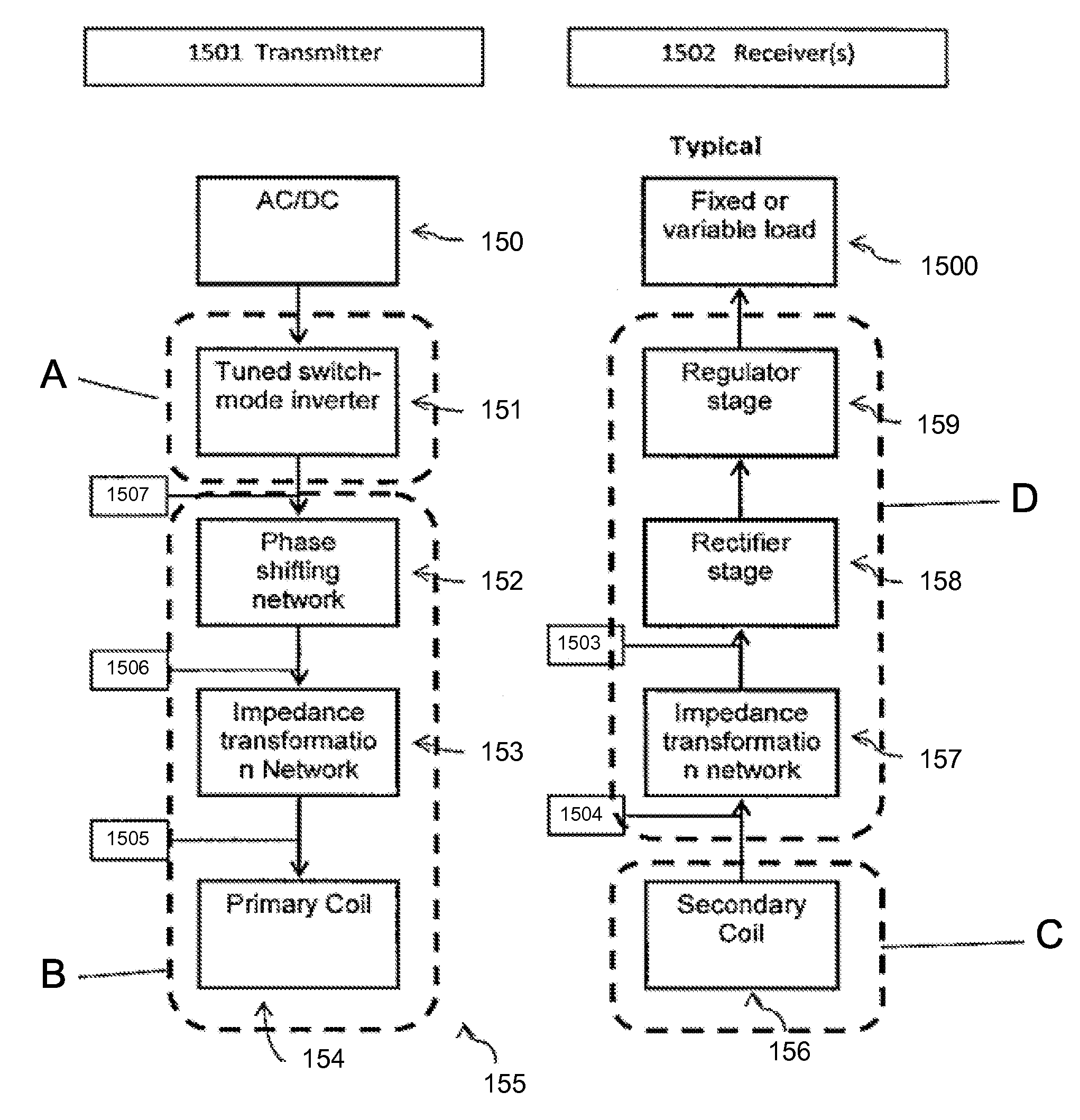
[0020]1) Reactance shifting and phase angle control: a reactance is added to the resistance looking from the switch-mode supply through the load network. The reactance is shifted such that the phase angle looking from the switch-mode inverter into the load network is within a range that provides substantially soft-switching operation of the active device either when connected to or disconnected from one or more loads. Embodiments of the invention use the phase angle to control the power delivered by the inverter. Such embodiments can take advantage of the correlation between phase angle and load resistance. Changes in load resistance are transformed into a shift in the phase angle looking into the impedance transformation network. The output power response is more pronounced with respect to phase than with respect to load resistance (see FIG. 12). This enables the invention to match power delivery and more closely mimic the response of a traditional DC supply (see FIG. 13). In this method of operation, the contactless power system can deliver the necessary amount of power to the load. The soft-switching operation of the active device is preferably maintained for all load impedances.
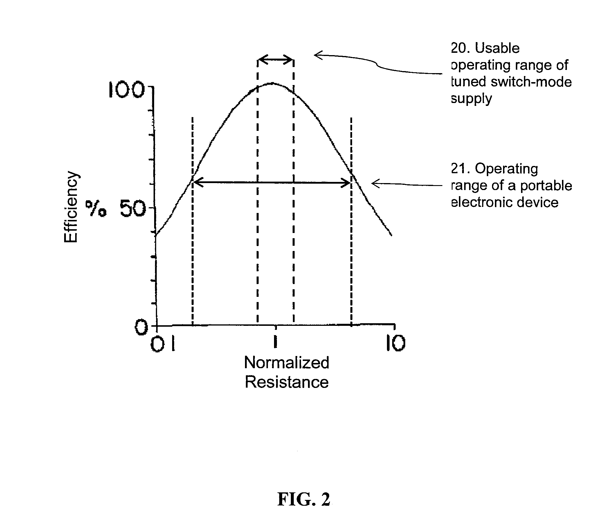
[0027]Embodiments of the invention can isolate the switch-mode supply from changes in load resistance in order to improve the predictability and stability of the output power. The isolation from changes can be accomplished by the implementation one or more filter networks such that the range of resistances presented by load appear much narrower at the output terminals of a switch-mode inverter. The switch-mode supply should see a resistance such that it is in a high efficiency mode of operation (see FIG. 2).
[0029]4) Coupling: at least one primary coil in the load network is inductively coupled to one or more secondary coils of the same load network. The primary coils can be configured in a spiral configuration and maybe designed with a variable pitch in order to create an even magnetic field distribution. The primary coils can be arranged in an array pattern with each coil in the array wound with an irregular shape so that the array has a substantially even magnetic field distribution. The secondary coils can be coupled to the primary coil in any position or orientation. The secondary coil can be adapted to attach to a load. In a preferred embodiment the secondary coil is adapted to attach to a portable electronic device. In specific embodiments, both the primary coil and the secondary coil are the same size to maximize coupling. In this example, and other specific embodiments, the receiver coil is significantly smaller than the primary coil, in order to allow the user to place the device in any orientation. It is desirable for the secondary coil to be much smaller than the primary coil, but the efficiency and power transfer capabilities start to degrade significantly if the receiver is too small, due to poor coupling. In this example the secondary is wound along a single path with minimal spacing between turns in order to minimize the occupied volume and ease integration.
[0034]The above equations neglect any 2nd order effects such as skin depth and proximity effects. A more in-depth analysis accounting for the above effects can be utilized. In an embodiment, litz wires can be used to mitigate such effects to the extent that they do not create significant discrepancies.
[0035]By using the combination of resistance isolation and phase angle control, a reliable, stable transmitter can power a variable load. First, the inverter preferably will not fail or overheat when the secondary coil is removed from the primary coil. Although a load detection scheme can be used to turn off the transmitter and reduce unloaded power losses, it can still be desirable for the unloaded power consumption to be sufficiently low. Since the coil voltage is unique to each load resistance as shown in FIG. 49, load detection and status can be easily acquired. To avoid false detection, the load detection and status can be verified by analyzing the supply current via a current sense resistor. Limiting unloaded power loss can be achieved by ensuring the unloaded transmitting load network has effective impedance similar to a high load resistance case (high impedance with large phase angle). From the schematic of the class E circuit in FIG. 44, it can be deduced that most of the power lost is due to the primary coil and inductor parasitic resistances as they are in the path of power transfer. Therefore, one way to reduce the unloaded power loss is to use an inductor with lower parasitic resistance.

Problems solved by technology

Because of size mismatches and restrictions on the use of bulky core materials, the coupling between the primary and secondary coils can be weak thereby reducing efficiency, power delivery, or both.
The variable impedance of a load device makes the implementation of contactless power system difficult.
r). Because of this, a load device's pre-existing power management control system can fail to appropriately regulate the power delivered to the load device which can lead to component fail
Due to the above described characteristics a contactless power system is likely to encounter one or more of the following problems: 1) over-voltage and / or under-voltage conditions throughout the circuit; 2) excess or inadequate power delivery to individual loads 3) power oscillations; 4) heat problems; and 5) low efficiency.
Notably, a class D inverter architecture does not share the unfavorable characteristics and resulting problems of the other soft-switched inverters.
1308-1314, October 2005) Control functionality adds to the cost and complexity of a system and detracts from the commercial viability.
Such communication systems also add undesirable cost to the system.
Contemporary batteries will not charge at temperatures over 50° C. These systems also add undesirable cost to the system.

Method used


Image

  • Method and apparatus for contactless power transfer
  • Method and apparatus for contactless power transfer
  • Method and apparatus for contactless power transfer

Examples


example 1

[0134]A high power, high-efficiency contactless power transfer system using the impedance transformation network and has been designed and fabricated using the subject impedance transformation network. The contactless transfer system requires minimal control to achieve the desired power delivery profile across a wide range of load resistances, while maintaining high efficiency to which helps to prevent overheating of components. This embodiment of the subject system includes more than one active device with independent gate drive to control power delivery. The system is able to achieve power delivery of 295 W to a load of 50Ω with a DC voltage of 121.5V and current of 2.43 A. The input current was current-limited at 3.25 A. The system efficiency at maximum power output is 75.7%. The system operates at a minimum of 77% efficiency across load resistances ranging from 60 to Ω 140Ω which corresponds to a high output power state. The system can be scaled to achieve higher output power if...

example 2

[0154]A primary coil parallel capacitor value in a specific embodiment can meet two constraints.

[0155]FIG. 24 offers a contrast to the preferred phase angle vs. load resistance trend shown in FIG. 21. The reference phase angle is approximately 80 degrees and decreases with load resistance. The phase angle 240 decreases with load resistance.

[0156]FIG. 25 shows the result of this mode of operation when there are no communication and control mechanisms in place. The power output increases with load resistance, which is exactly opposite the response of a fixed voltage DC supply 130 which is shown in FIG. 13.

[0157]FIG. 27 shows the real and reactive components of the impedance as seen looking into the receiver side impedance transformation network, where the impedance characteristic at this point is measured from a system operating in an undesirable range.

[0158]FIG. 28 shows the real and reactive components of the impedance as looking into the primary coil, where the impedance characteri...


PUM

PropertyMeasurementUnit
frequenciesaaaaaaaaaa
temperaturesaaaaaaaaaa
phase angleaaaaaaaaaa

Abstract

Embodiments of the subject invention pertain to a method and apparatus for contactless power transfer. A specific embodiment relates to an impedance transformation network, a new class of load network for application to a contactless power system. Embodiments of the impedance transformation network enable a contactless power system to operate without encountering the common problems of: 1) over-voltage and / or under-voltage conditions; 2) over-power and / or under-power conditions; 3) power oscillations; and 4) high heat dissipation.

Description

CROSS REFERENCE TO RELATED APPLICATION[0001]This application claims priority to “METHOD AND APPARATUS FOR CONTACTLESS POWER TRANSFER,” having serial number PCT / US2009 / 046648, filed on Jun. 8, 2009, which claims priority to and the benefit of U.S. Provisional Application No. 61 / 059,663, filing date Jun. 6, 2008.BACKGROUND OF INVENTION[0002]In recent years, inductive charging technology has become a leading candidate to eliminate power cables. Inductive power systems and other contactless power systems typically use one or more transmitters to send power to one or more receivers. Electronic devices with contactless power receivers can be powered or charged by being positioned in close proximity to a contactless power transmitter. Such systems have been designed and implemented.[0003]Contemporary contactless power systems are make use of switch-mode inverters, such as the Class, D, DE, E, E−1, F, F−1, EF, EF2, EF3, Phi. The switch-mode inverter converts DC voltage that is provided by a...

Claims


Application Information

Patent Timeline
Patent Type & Authority Patents(United States)
IPC IPC(8): H01F37/00H01F38/00H01F27/42
CPCH02J5/005H02J7/0047H02J50/402H02J50/80H02J7/00308H02J7/00304H02J50/12
Inventor LOW, ZHEN NINGLIN, JENSHANCHINGA, RAUL ANDRES
Owner UNIV OF FLORIDA RES FOUNDATION INC
Why Eureka
Try Eureka