Dynamic power management via DIMM read operation limiter

a technology of dynamic power management and dimm read, which is applied in the direction of liquid/fluent solid measurement, instruments, sustainable buildings, etc., can solve the problems of reducing the airflow and cooling capacity at the chip level, increasing the power dissipation per dimm, and not increasing the volume of space allocated to the drams on the memory modules

Inactive Publication Date: 2006-08-10
IBM CORP
View PDF6 Cites 207 Cited by
  • Summary
  • Abstract
  • Description
  • Claims
  • Application Information

AI Technical Summary

Benefits of technology

[0015] Disclosed is a method and system for enabling directed temperature / power management at the DIMM-level and / or DRAM-level utilizing intelligent scheduling of memory access operations received at the memory controller. The invention manages power usage by lower-level memory devices and prevents overheating (hot spots) at the individual DIMM and / or DRAM levels, while enabling efficient distribution of the memory access commands to the various DIMMs in a multi-DIMM memory subsystem to enable maximum use of the available memory channel bandwidth and DIMM data bus bandwidth.
[0019] In addition, since power and thermal variations in a system are not instantaneous, the memory controller can be programmed to track the average power utilization over a programmable window of time rather than an instantaneous power value. This allows the access pattern to briefly exceed the limit set by the system in the power management logic but, on a broader average, the power utilization will stay under the limit. System performance is also improved by reducing the number of times that operations are throttled in the system.
[0022] The dynamic feedback allows the system to adjust its throttling mechanism based on actual power requirements of the installed set of DIMMs. This dynamic adjustment is important since DRAMs from different suppliers have different power profiles and because physical environments may vary, allowing for more or less cooling capabilities in the system.
[0024] According to this fourth function, the distribution of power across the DIMMs in the system is maintained by dividing the address space across all the individual DIMMS within the system. Thus, rather than provide sequential groupings of consecutive addresses in each individual DIMM, each sequence of addressed is shared across multiple DIMMs so that access to a sequence of addresses hit multiple DIMMs in sequence rather than a single DIMM. This configuration of the address space also allows DIMMs to be busy less frequently when a next access operation is received since the next operation does not target the same DIMM as the previous memory access operation.

Problems solved by technology

In addition, due to physical constraints of the overall computer systems, the volume of space that is allocated to the DRAMs on the memory modules has not increased much over time.
The resulting increased density results in an increase of the power dissipation per DIMM, while the space limitations have reduce the airflow and cooling capacity at the chip level.
The main sources of power consumption are the DRAMs and the control chips on the DIMMs.
However, there is little that can be done to reduce this power consumption.
While these power consumption values may appear small, a large server system may have tens of thousands of DRAM chips installed.
With potentially thousands of DRAMs packed into a relatively small space and each consuming some amounts of power, the possibility of the memory chips overheating becomes a major design concern.
Designing cooling systems to provide sufficient cooling capacity for these high density memory systems is extremely difficult as the cooling systems have to keep up with the increasing density of these memory chips.
Occasionally, during operation, several DRAMs in close vicinity to each other may be continually in the operating state (as operations targeting the DRAMs are issued), leading to the creation of a hot spot (i.e., localized overheating) within the memory subsystem.
While the above described power management / control techniques provide general cooling and maintenance of maximum power usage for the memory subsystem, there is currently no way of predicting where hot spots will occur within the different memory modules.
Thus, the above described power management mechanisms are not always able to adequately provide limits on power usage or sufficient cooling directed at these potential hot spots, rather then general power management directed at the entire memory subsystem.

Method used


Image

  • Dynamic power management via DIMM read operation limiter
  • Dynamic power management via DIMM read operation limiter
  • Dynamic power management via DIMM read operation limiter

Examples


Embodiment Construction

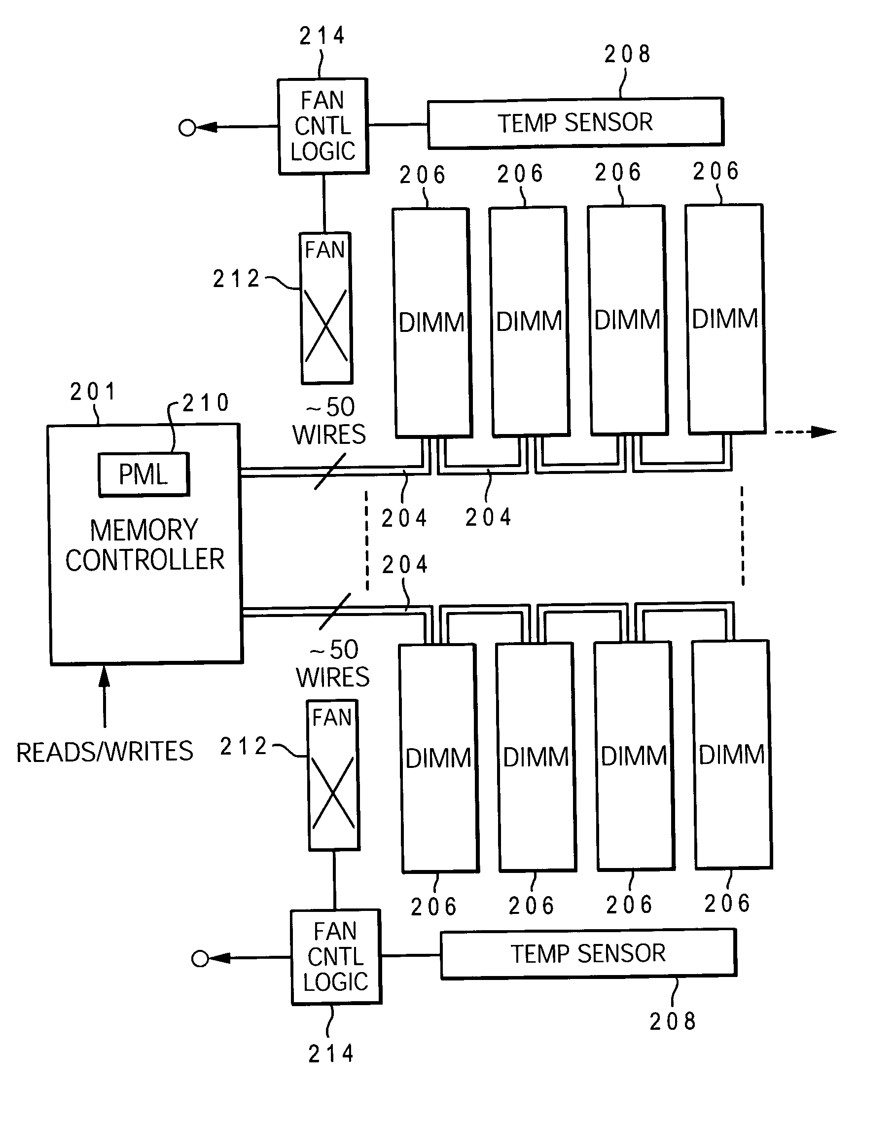
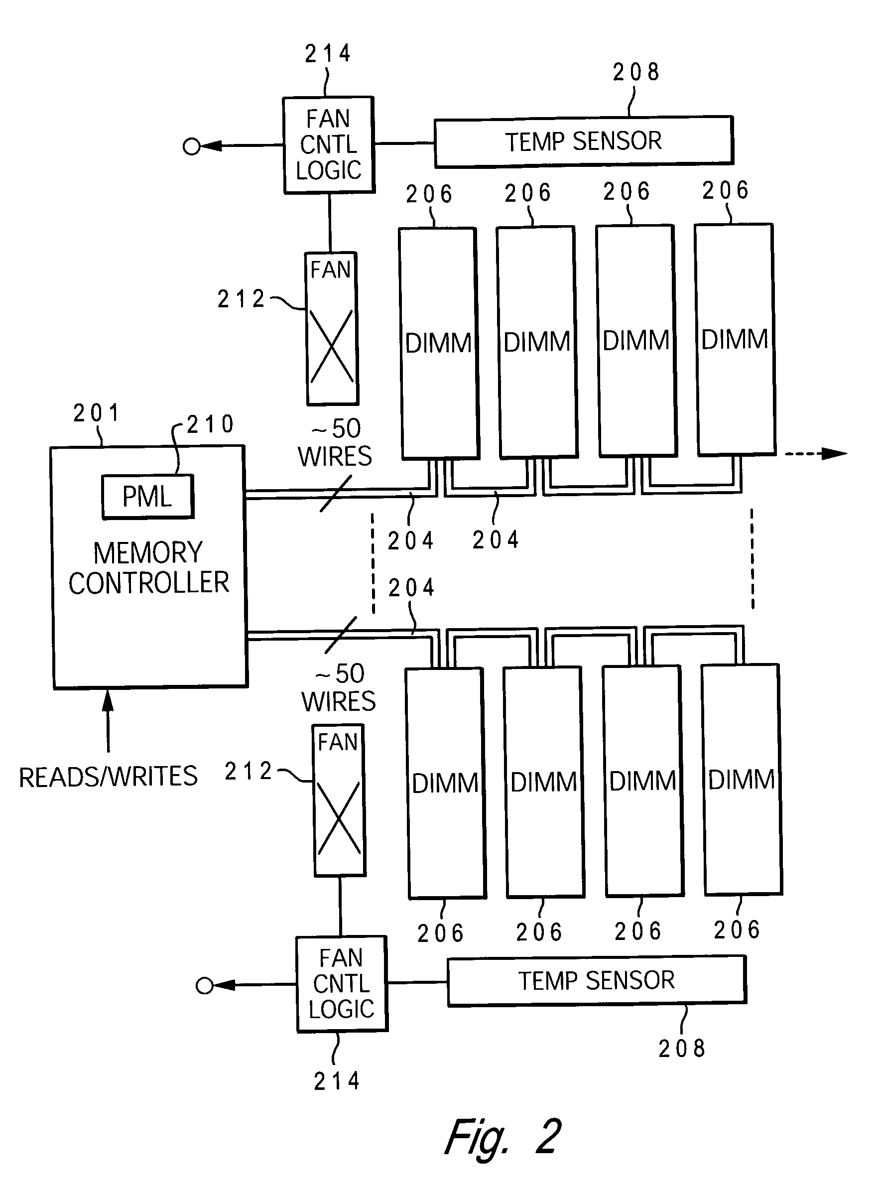
[0032] The present invention provides a method and system for enabling directed temperature / power management at the DIMM-level and / or DRAM-level utilizing intelligent scheduling of memory access operations received at the memory controller. The invention manages power usage by lower-level memory devices and prevents overheating (hot spots) at the individual DIMM and / or DRAM levels, while enabling efficient distribution of the memory access commands to the various DIMMs in a multi-DIMM memory subsystem to enable maximum use of the available system data bus bandwidth and DIMM data bus bandwidth.

[0033] Hot spots within the memory subsystem, caused by operating the DIMMs / DRAMs above predetermined / preset threshold power / temperature, are avoided / controlled by logic within the memory controller. The memory controller logic throttles the number / frequency at which commands (read / write operations) are issued to the specific DIMM / DRAM based on the specific DIMM / DRAM reaching the preset thresh...


PUM


Abstract

A method and system for enabling directed temperature / power management at the DIMM-level and / or DRAM-level utilizing intelligent scheduling of memory access operations received at the memory controller. Hot spots within the memory subsystem, caused by operating the DIMMs / DRAMs above predetermined / preset threshold power / temperature values for operating a DIMM and / or a DRAM, are avoided / controlled by logic within the memory controller. The memory controller logic throttles the number / frequency at which commands (read / write operations) are issued to the specific DIMM / DRAM based on feedback data received from the specific DIMM / DRAM reaching the preset threshold power usage value.

Description

CROSS REFERENCE TO RELATED APPLICATION(S) [0001] The present invention is related to the following commonly assigned, co-pending applications: “Streaming Reads in a Cascaded Memory Subsystem With Buffered Memory Modules,” Serial No. ______, Attorney Docket No. AUS920041030US1; and “Power Management Via DIMM Read Operation Limiter,” Serial No. ______, Attorney Docket No. AUS920041032US1; each filed concurrently herewith. The contents of the above applications are incorporated herein by reference.BACKGROUND OF THE INVENTION [0002] 1. Technical Field [0003] The present invention relates generally to computer devices and in particular to operating parameters of memory subsystems. Still more particularly, the present invention relates to a method and system that provides direct management of power usage by memory modules within a memory subsystem. [0004] 2. Description of Related Art [0005] Increases in processor performance and the proliferation / development of multi-core, multi-threaded...

Claims


Application Information

Patent Timeline
Patent Type & Authority Applications(United States)
IPC IPC(8): G06F1/32
CPCG06F1/206Y02B60/1275G06F1/3225Y02D10/00
Inventor BRITTAIN, MARK ANDREWCORDERO, EDGAR ROLANDOFIELDS, JAMES STEPHEN JR.MAULE, WARREN EDWARDRETTER, ERIC EUGENE
Owner IBM CORP
Why Eureka
Try Eureka