Long-fibre-reinforced-joints-composite thrust reverser cascade

a composite cascade and fibre reinforced joint technology, applied in the direction of machines/engines, other domestic articles, power plant exhaust arrangements, etc., can solve the problems of multiple operating constraints of the cascade, unfavorable material selection, and high manufacturing cost, so as to reduce the risk of delamination, improve the mechanical properties of the cascade, and increase the mechanical strength

Active Publication Date: 2021-09-16
DEDIENNE MULTIPLASTURGY GRP +1
View PDF0 Cites 0 Cited by
  • Summary
  • Abstract
  • Description
  • Claims
  • Application Information

AI Technical Summary

Benefits of technology

[0030]The crossing of the fibre bundles gives the invention an increased mechanical strength, reducing the risk of delamination at the interface between strongbacks and vanes.
[0031]The improvemen

Problems solved by technology

Cascades are subject to multiple operating constraints.
Over the last thirty years, industrial growth of materials manufacturing for aeronautics has unceasingly provided increasingly suited candidate materials to this kind of specification.
However, materials industrial processing for specifically forming the mutually overhanging cells geometries (also referred to as undercuts) of a thrust reverser cascade raises significant technical obstacles that have to be overcome, thus justifying the scarcity of hitherto successful applications.
Despite its success, this manufacturing process is, on the one hand, costly in terms of qualified workforce, and, on the other hand, because of the relatively low geometrical precision of the repeated manual operations, accompanied with geometrical manufacturing tolerances that are detrimental in terms of productivity and in terms of scrap rates.
U.S. Pat. No. 4,596/621 application discloses a manufacturing process which is inclusive of a slide-moulding step enabling the removal from mould of solely removable aerodynamic cavities sh

Method used


Image

  • Long-fibre-reinforced-joints-composite thrust reverser cascade
  • Long-fibre-reinforced-joints-composite thrust reverser cascade
  • Long-fibre-reinforced-joints-composite thrust reverser cascade

Examples


Embodiment Construction

[0020]There is a need to further improve thrust reverser composite cascades, and the processes for manufacturing such cascades, in order notably to remedy all or some of the drawbacks of known composite cascades, and in particular benefit from a cascade that is strong, lightweight and has low geometrical manufacturing tolerances.

SUMMARY OF THE INVENTION

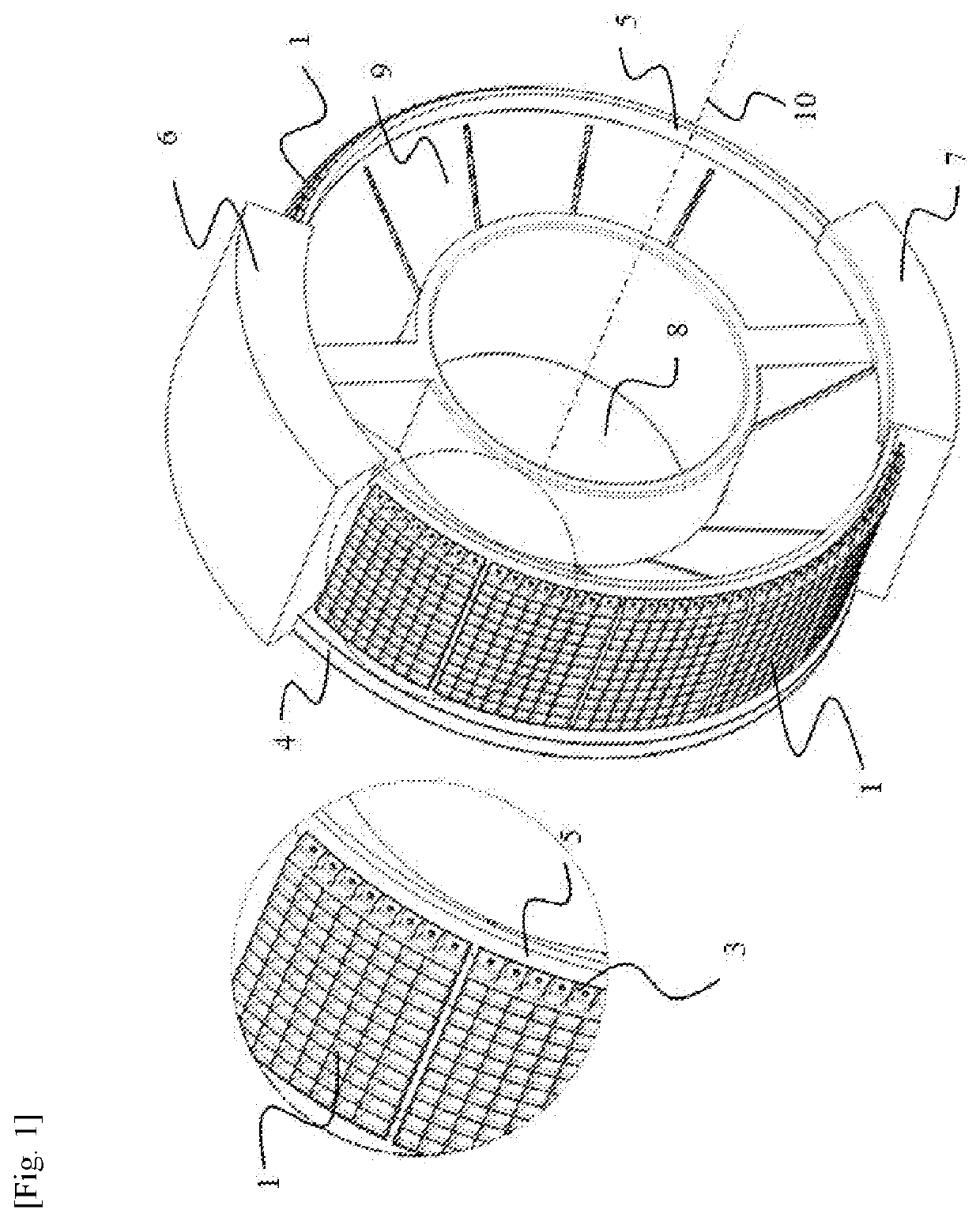
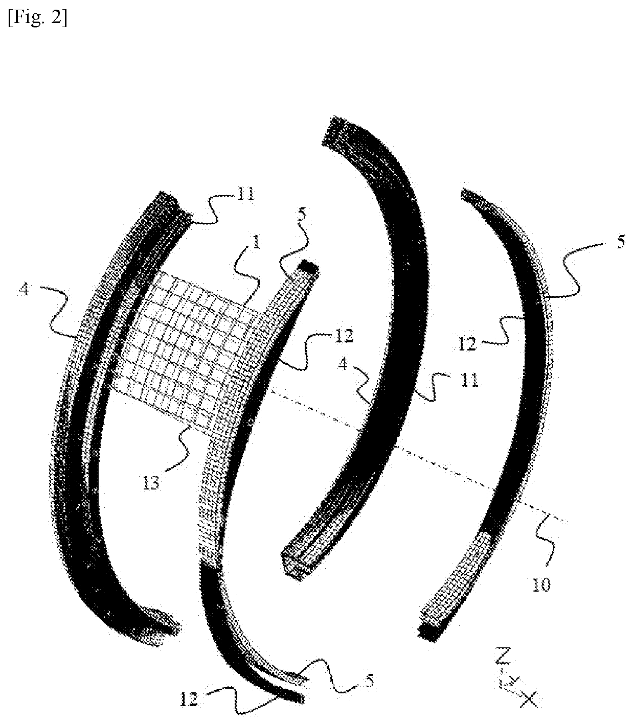
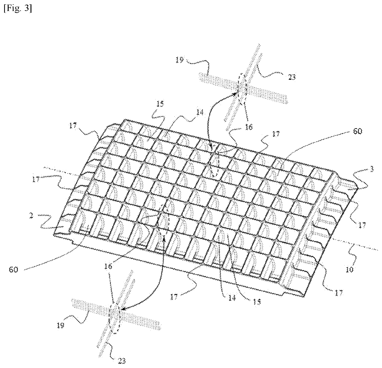
[0021]The invention aims to address this need for improvement and succeeds in this, according to a first of its aspects, owing to a thrust reverser composite cascade, comprising at least one longitudinal wall and transverse walls connecting to this longitudinal wall, characterized in that the longitudinal wall comprises at least one continuous longitudinal fibre bundle and the transverse walls each comprise at least one continuous transverse fibre bundle crossing the longitudinal bundle so that the intersections of the transverse and longitudinal walls can be structurally bridged in both directions by the reinforcing continuous longit...


PUM

PropertyMeasurementUnit
Angleaaaaaaaaaa
Angleaaaaaaaaaa
Thicknessaaaaaaaaaa

Abstract

Thrust reverser composite cascade (1), comprising at least one longitudinal wall (15) and transverse walls (14) connecting to this longitudinal wall, characterized in that the longitudinal wall comprises at least one continuous longitudinal fibre bundle (19) and the transverse walls each comprise at least one continuous transverse fibre bundle (23) crossing the longitudinal bundle, so that the intersections (16) of the transverse and longitudinal walls are structurally bridged in both directions by the reinforcing continuous longitudinal and transverse fibre bundles.

Description

TECHNICAL FIELD[0001]The present invention focuses on a thrust reverser composite cascade, and its manufacturing process.TECHNICAL BACKGROUND[0002]Thrust reversers are used to shorten landing aircrafts' braking range, by generating a counter-thrust, obtained by turning forward a portion of the engine exit air flow.[0003]Cascade thrust reversers comprise cascades for orienting the exit air flow outward the nacelle following accurate flow paths, in order to ensure aerodynamic performance by counter-thrust orientation. Cascade geometry is made of several parallel and equidistant vanes crossing several parallel and equidistant strongbacks and defining cells. Strongbacks are longitudinal structures to which transverse structures of vanes are attached, and routing counter-thrust loads outward the cascades, generally towards nacelle forward frame. These structures are potentially profiled to enable some aerodynamic function. Vanes are transverse structures to strongbacks, generally profile...

Claims


Application Information

Patent Timeline
IPC IPC(8): F02K1/56B64D33/04
CPCF02K1/56B64D33/04F05D2230/31F05D2240/129F05D2230/20F05D2220/323F02K1/72F05D2230/50F05D2300/603F05D2300/6034Y02T50/60B29C70/46B29L2031/08B29D28/005B29C70/205B29C70/06
Inventor CALME, ODNELJACQUEMIN, NICOLASLARROUY, FRÉDÉRICRIBOUR, FRANÇOIS
Owner DEDIENNE MULTIPLASTURGY GRP
Why Eureka
Try Eureka