Horn antenna for a radar device

a radar device and horn technology, applied in the direction of antennas, antenna details, electrical devices, etc., can solve the problems of sealing and cleaning problems, different thermal expansions of hollow horn sections and dielectric filling bodies, and the interference of the top of the vessel with the wanted echo of the filling product in the vessel, so as to facilitate the application of the cover

Inactive Publication Date: 2014-11-04
SIEMENS AG
View PDF11 Cites 237 Cited by
  • Summary
  • Abstract
  • Description
  • Claims
  • Application Information

AI Technical Summary

Benefits of technology

[0016]The dielectric filling body is at one end centered in the tubular waveguide section and at the other end by the collar so that the dielectric filling body is movable longitudinally to absorb the differential thermal expansion of the different antenna materials over the whole operating temperature range. The spring presses the filling body against the cover thus mechanically stabilizing the cover and leaving no gap between the filling body and the cover. The spring is in remote position behind the aperture of the antenna and cannot affect the antenna's radiation characteristic.
[0019]For centering the metal body and the dielectric cover, and for providing a seal to prevent excess condensation from migrating down to the tip of the antenna, the dielectric filling body may have a peripheral groove receiving a seal between the metal body and the dielectric cover.

Problems solved by technology

The major drawback of the conventional horn antennas disclosed in the U.S. 2009 / 0212996 A1 and FIG. 8 of U.S. Pat. No. 6,661,389 is that each of these disclosed horn antennas do not protrude into the vessel so that reflections from the mounting flange or the top of the vessel may interfere with the wanted echo from the filling product in the vessel.
The conventional horn antenna depicted in FIG. 7 of U.S. Pat. No. 6,661,389 has the problem in that the hollow horn section and the dielectric filling body have different thermal expansions.
The known antenna further shows a two-part design on the process side that may cause sealing and cleaning problems.

Method used


Image

  • Horn antenna for a radar device
  • Horn antenna for a radar device

Examples


Embodiment Construction

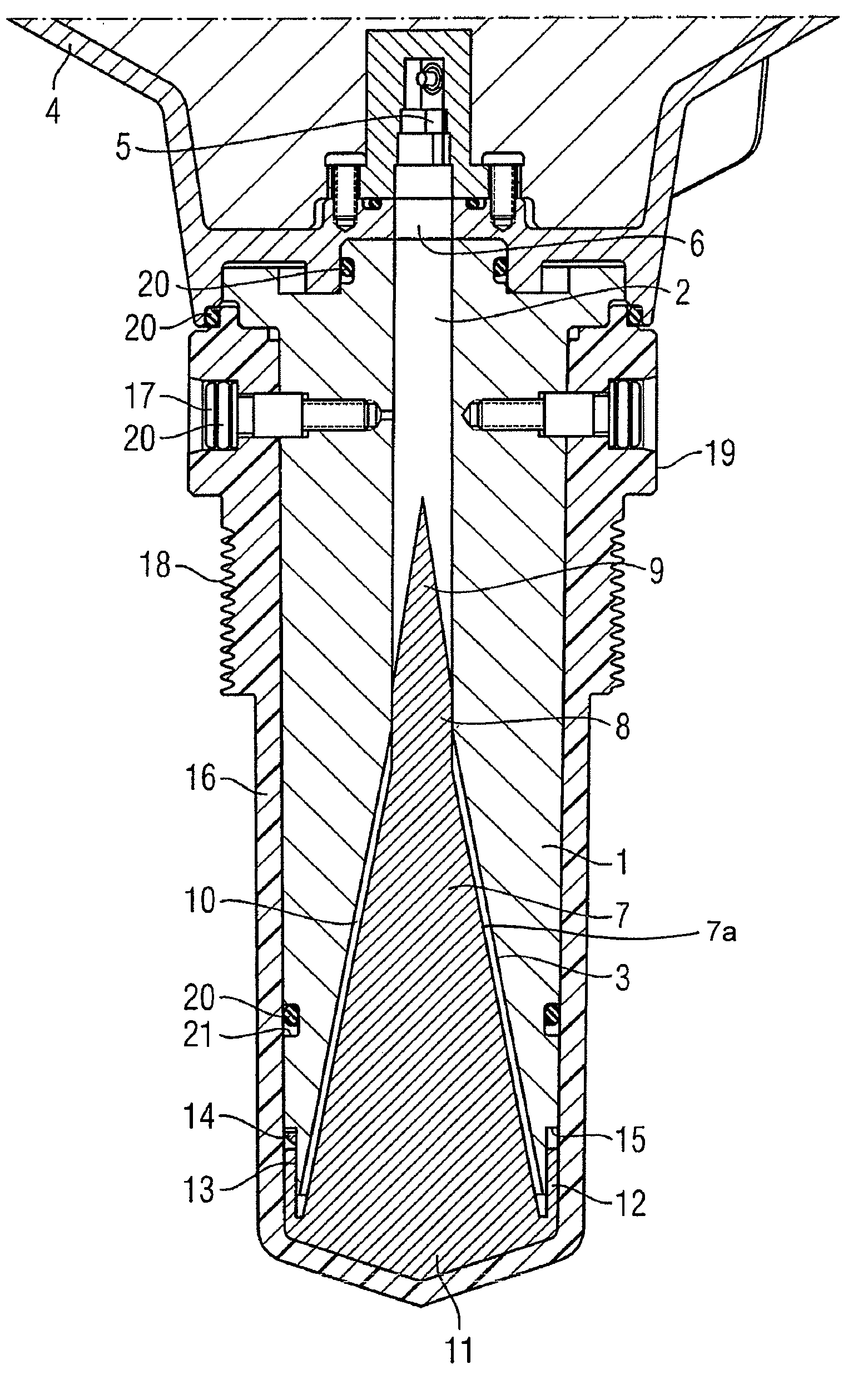
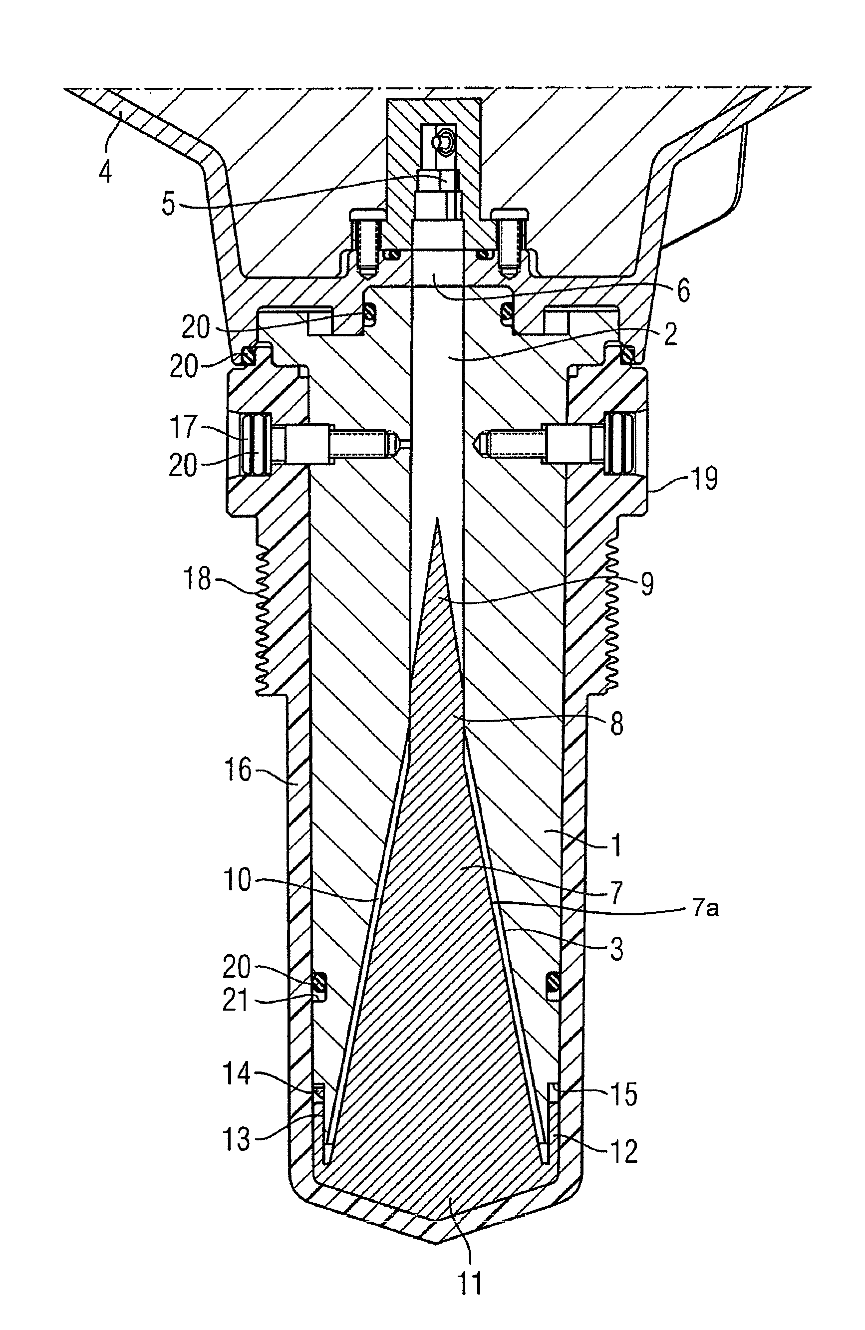
[0024]The horn antenna depicted in the FIGURE comprises a cylindrical metal body 1, preferably of aluminum, in which a tubular waveguide section 2 and an adjoining cone-like horn section 3 are formed. The metal body 1 is attached to a housing 4 of a radar level transmitter. As known from, e.g., U.S. Pat. No. 7,453,393 B2, a microwave energy signal supplied by a High Frequency (HF) module (not shown) located inside the housing 4 is transferred to a waveguide transition 5 that connects to a short section of a circular waveguide 6 machined in the wall of the housing 4. The microwave energy signal is forwarded to the tubular waveguide section 2 that has the same diameter as the circular waveguide 6. Centering elements are provided to ensure alignment and good electrical contact between the two waveguides 2, 6 to reduce reflections and maximize transferred power. The signal is directed to the horn section 3 from the tubular waveguide section 2.

[0025]The horn section 3 is filled with a di...


PUM


Abstract

A horn antenna for a radar device comprising a metal body having a tubular hollow waveguide section opening into a hollow horn section, a dielectric filling body filling up the inner space of the horn section, and a dielectric cover, wherein the horn antenna is configured to protrude in a measurement environment, protected from highly aggressive process environments and is usable over a wide temperature range.

Description

BACKGROUND OF THE INVENTION[0001]1. Field of the Invention[0002]The invention relates to radar antennas and, more particularly, to a horn antenna for a radar device comprising a metal body containing a tubular hollow waveguide section which opens into a hollow horn section, a dielectric filling body filling up the inner space of the horn section, and a dielectric cover which is provided surrounding the metal body and covering the filling body at the aperture of the horn section as a protective covering for the horn antenna.[0003]2. Description of the Related Art[0004]FIG. 7 of U.S. Pat. No. 6,661,389 discloses a conventional horn antenna.[0005]In general, microwave pulses, which have been generated by High Frequency (HF) energy coupled in, are radiated by a horn antenna, which also is known as cone antenna. In a combined transmitting and receiving system of a level measuring device equipped with such an antenna, the pulses reflected by a filling product are detected, and the distanc...

Claims


Application Information

Patent Timeline
Patent Type & Authority Patents(United States)
IPC IPC(8): H01Q13/00H01Q1/22H01Q19/08
CPCH01Q19/08H01Q1/225
Inventor COUPLAND, TIMSERBAN, GABRIEL
Owner SIEMENS AG
Why Eureka
Try Eureka