Zero-profile interbody spacer and coupled plate assembly

a technology of coupled plate and spacer, which is applied in the field of spinal implants, can solve problems such as adverse impact on the performance of implants, and achieve the effect of preventing over-insertion

Active Publication Date: 2010-06-10
DEPUY SYNTHES PROD INC
View PDF102 Cites 242 Cited by
  • Summary
  • Abstract
  • Description
  • Claims
  • Application Information

AI Technical Summary

Benefits of technology

[0018]The implant preferably also includes first and second stops to prevent over insertion of the implant during implantation and to assist in securing a position of the implant during insertion of the first and second bone fixation elements, the first stop extending superiorly of the top surface of the plate portion for contacting the superior vertebral body, the second stop extending inferiorly of the bottom surface of the plate portion for contacting the inferior vertebral body. The first and second stops are preferably integrally formed with the plate portion.
[0019]In another exemplary embodiment, the implant sized and adapted for insertion into an intervertebral disc space between superior and inferior vertebral bodies includes (a) first and second bone fixation elements; (b) a spacer portion including a top surface for contacting the superior vertebral body, a bottom surface for contacting the inferior vertebral body, a first side surface, a second side surface, a leading surface and a trailing surface; and (c) a plate portion coupled to the spacer portion. The plate portion includes a top surface, a bottom surface, a first side surface, a second side surface, a leading surface, a trailing surface, and first and second bone fixation holes. The first and second bone fixation holes sized and adapted for receiving the first and second bone fixation elements, respectively. The first bone fixation hole is angled so that the first bone fixation element engages the superior vertebral body and

Problems solved by technology

Both screw back-out and over-insertion of the implant into a prepared d

Method used


Image

  • Zero-profile interbody spacer and coupled plate assembly
  • Zero-profile interbody spacer and coupled plate assembly
  • Zero-profile interbody spacer and coupled plate assembly

Examples


Embodiment Construction

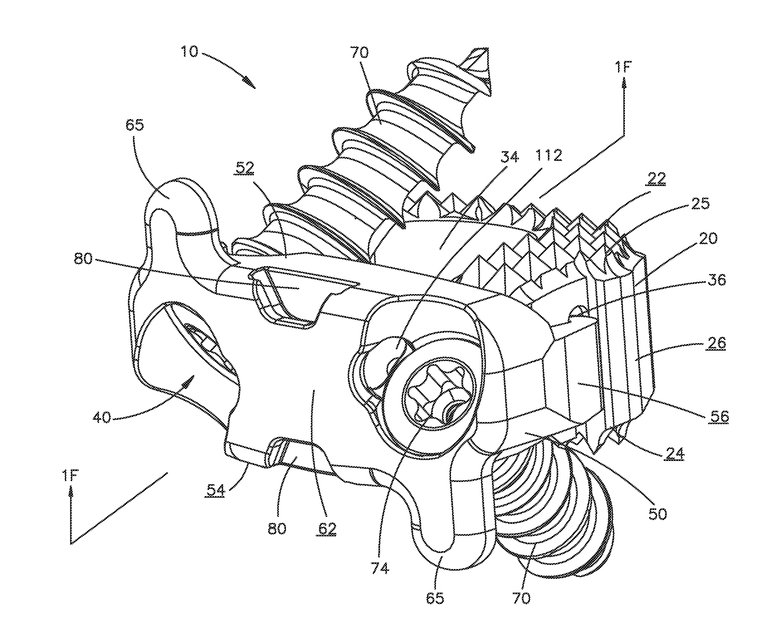
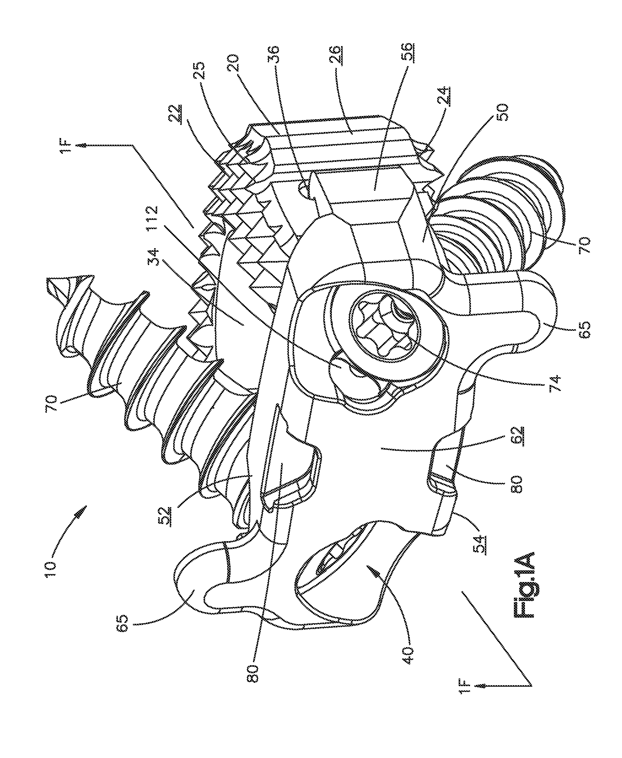
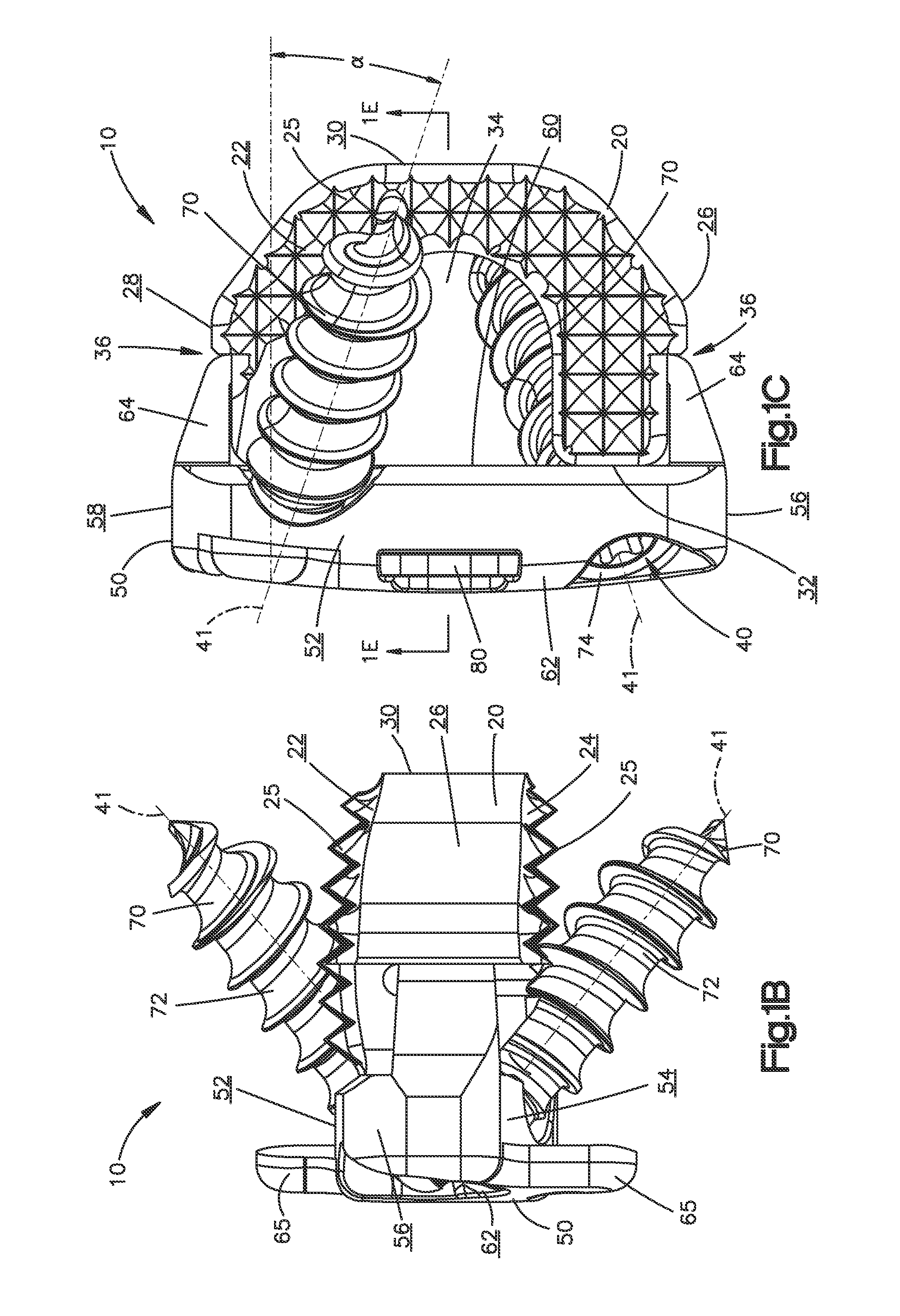
[0051]Certain terminology is used in the following description for convenience only and is not limiting. The words “right”, “left”, “lower” and “upper” designate directions in the drawings to which reference is made. The words “inwardly” or “distally” and “outwardly” or “proximally” refer to directions toward and away from, respectively, the geometric center of the implant and related parts thereof. The words, “anterior”, “posterior”, “superior,”“inferior” and related words and / or phrases designate preferred positions and orientations in the human body to which reference is made and are not meant to be limiting. The terminology includes the above-listed words, derivatives thereof and words of similar import.

[0052]Similar reference numerals will be utilized throughout the application to describe similar or the same components of each of the preferred embodiments of the implant described herein and the descriptions will focus on the specific features of the individual embodiments that...


PUM

PropertyMeasurementUnit
Angleaaaaaaaaaa
Widthaaaaaaaaaa
Heightaaaaaaaaaa

Abstract

An implant for insertion into a disc space between vertebrae, wherein the implant includes a spacer portion, a plate portion coupled to the spacer portion, two bone fixation elements for engaging the vertebrae and a retention mechanism for preventing the bone fixation elements from postoperatively backing-out of the plate portion. The retention mechanism may be in the form of a spring biased snapper element that is biased into communication with the bone fixation elements so that once the bone fixation element advances past the snapper element, the snapper element is biased back to its initial position in which the snapper element interfaces with the bone fixation elements. Alternatively, the retention mechanism may be in the form of a propeller rotatable between a first position in which the bone fixation elements are insertable to a second position where the bone fixation elements are prevented from backing-out.

Description

CROSS REFERENCE TO RELATED APPLICATIONS[0001]This application claims priority to U.S. Provisional Patent Application No. 61 / 112,441, filed Nov. 7, 2008, entitled “Zero-Profile Interbody Spacer and Coupled Plate Assembly” and U.S. Provisional Patent Application No. 61 / 139,920, filed Dec. 22, 2008, entitled “Screw and Plate Locking Mechanisms for Smaller Bone Plates”, the contents of which are hereby incorporated by reference in their entirety.BACKGROUND OF THE INVENTION[0002]Intervertebral implants including interbody spacer portions and mechanically coupled plate portions are known in the art for restoring disc height, allowing fusion to occur between the adjacent vertebral bodies, and for providing stable fixation during healing.[0003]It is desirable to construct a zero-profile implant wherein bone fixation elements that secure the implant to the vertebral bodies are blocked from backing-out of the bone and / or plate.[0004]Additionally, it is desirable to construct a zero-profile im...

Claims


Application Information

Patent Timeline
IPC IPC(8): A61F2/44
CPCA61B17/1728A61B17/88A61B17/8033A61B17/8042A61B17/8052A61B17/8057A61B17/86A61F2/30965A61F2/4465A61F2/4611A61F2002/30387A61F2002/305A61F2002/30505A61F2002/30507A61F2002/30517A61F2002/30576A61F2002/30604A61F2002/30787A61F2002/30794A61F2002/30841A61F2002/4475A61F2220/0025A61F2310/00017A61F2310/00023A61F2310/00029A61F2310/00131A61F2310/00407A61F2310/00796A61B17/1757A61F2220/0016A61F2230/0034A61F2002/3079A61F2002/30593A61B17/809A61B17/7059A61F2/4455A61F2002/448A61F2002/4615
Inventor MCDONOUGH, WILLIAM P.STRAUSBAUGH, WILLIAM L.BONNER, CHRISTOPHERPEPE, THOMASMEILI, RALPHHUNZIKER, MARKUSJEGER, MICHAELKUEENZI, THOMASKOCH, DAVIDPONZER, RAINERRICHTER, JOERNBERGER, ROGER
Owner DEPUY SYNTHES PROD INC
Why Eureka
Try Eureka