
Pickup caps for electrical connectors

a technology of electrical connectors and pick-up caps, applied in the field of pick-up caps, to achieve the effect of facilitating lead-in

Active Publication Date: 2009-11-24
FCI AMERICAS TECH LLC
View PDF35 Cites 11 Cited by
  • Summary
  • Abstract
  • Description
  • Claims
  • Application Information

AI Technical Summary

Benefits of technology

"The invention is a pickup cap for an electrical connector. It has a flat body with legs that fit into slots in the connector housing. The legs have friction pads that fit snugly into the slots, securing the pickup cap to the connector. The pickup cap can be easily inserted and has protrusions to prevent over-inserting it. The friction pads have tapered ends to make it easier to insert the pickup cap into the connector housing. The slots are chamfered to guide the friction pads into place. This design ensures a secure and easy-to-use pickup cap for electrical connectors."

Problems solved by technology

Consequently, when the pickup cap is received into the connector housing, the legs may bow slightly, causing friction between the friction pads and slots to secure the pickup cap to the connector.

Method used


Image

  • Pickup caps for electrical connectors
  • Pickup caps for electrical connectors
  • Pickup caps for electrical connectors

Examples


Embodiment Construction

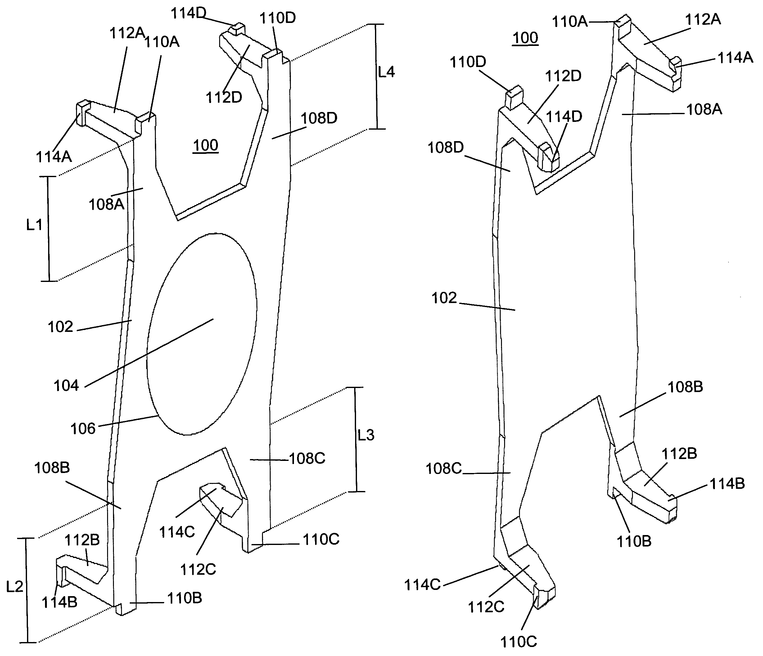
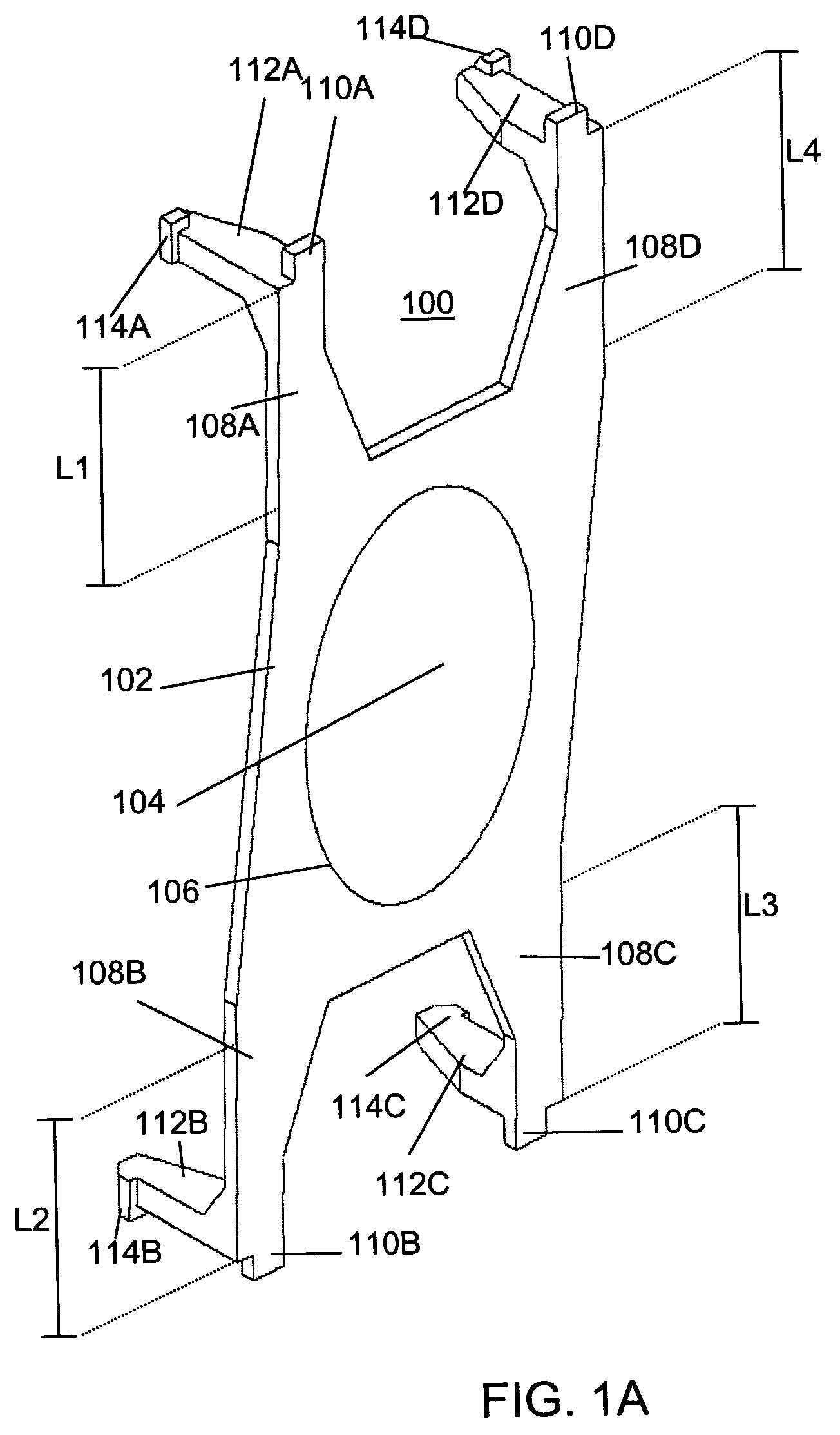
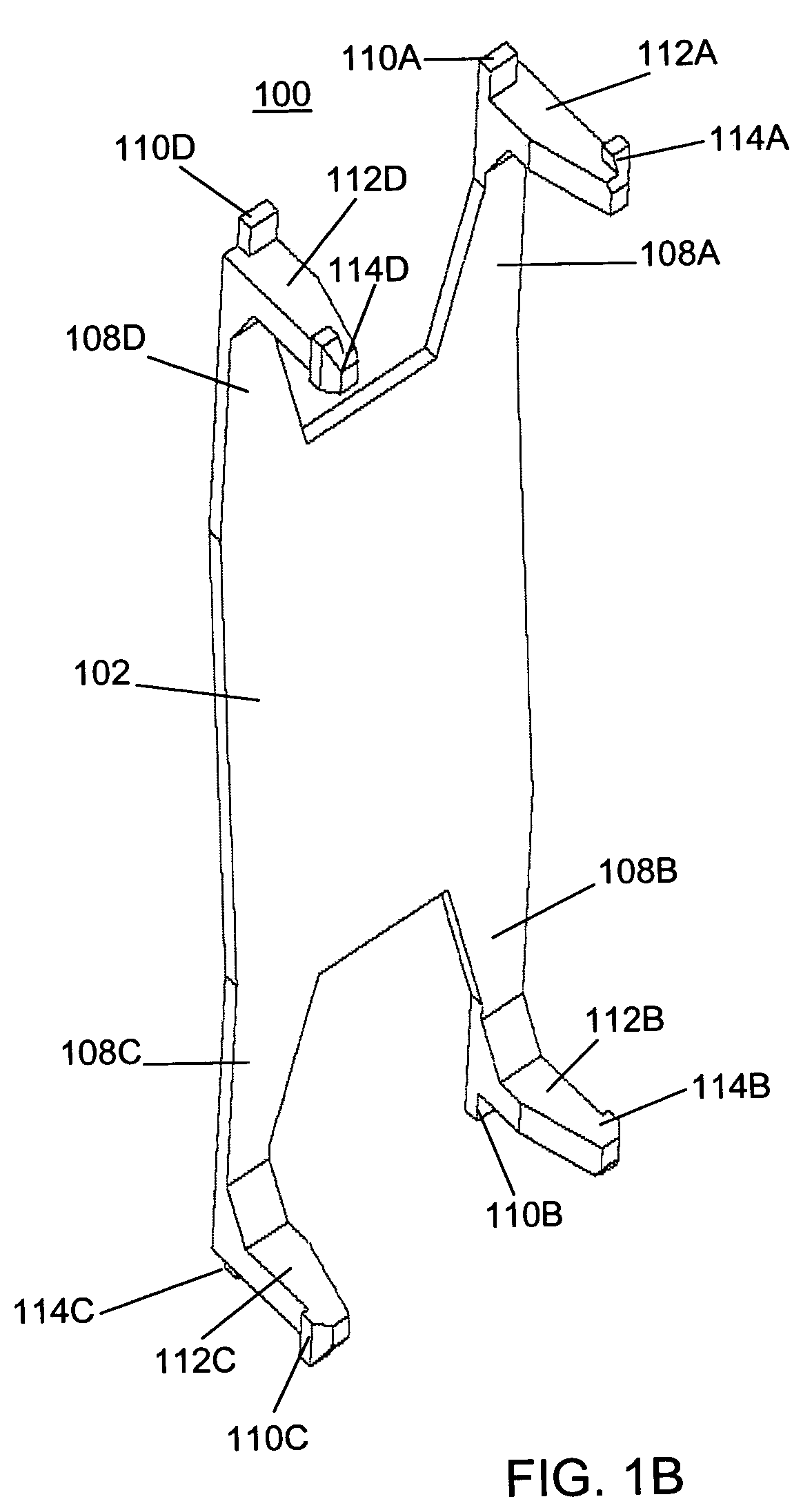
[0016]FIGS. 1A through 1E depict an illustrative embodiment of a pickup cap 100 according to the invention. The pickup cap 100 may be formed as a single piece of plastic, and may be injection molded, using well-known techniques. As shown, the pickup cap 100 may have a planar body portion 102. The body portion 102 may have a thickness of about 0.5 mm. The body portion may define a pickup portion 104. The pickup portion 104 may be formed such that a vacuum suction nozzle may engage the pickup cap, potentially for lifting, positioning, and placing.

[0017]The body portion 102 may include one or more extensions 108A-D. The extensions 108A-D may be flexible extensions that extend in the plane defined by the body portion 102. As shown, each extension 108A-D may extend from a respective corner of the body portion 102. Each extension may have a respective length, L1-L4 (i.e., the distance by which the extension extends beyond the planar central portion of the body portion 102). The farther th...


PUM


Abstract

A pickup cap for an electrical connector is disclosed. The pickup cap may include a planar body portion and a plurality of opposing legs extending from a side of the body portion. A respective friction pad may extend from each leg. The friction pads may be received into complementary slots in the housing of an electrical connector. Friction between the friction pads and walls that define the slots may be sufficient to secure the pickup cap to the connector. The planar body portion may include a pickup portion. When the pickup cap is received into the connector housing, the legs may bow slightly. The pickup portion, however, may remain generally planar, and generally parallel to the mating plane defined by the vertical connector, even when the pickup cap is fully inserted into the connector housing.

Description

FIELD OF THE INVENTION[0001]The invention relates to pickup caps that can be mounted on an electrical connector and held by a device such as a vacuum nozzle, so that the electrical connector can be lifted and moved during manufacturing and other operations.BACKGROUND OF THE INVENTION[0002]Electrical connectors are commonly lifted and positioned on a mounting surface using automated equipment referred to as “pick and place” equipment. The pick and place equipment typically includes a vacuum nozzle mounted on an arm or other movable structure. A pickup cap is usually placed on the connector to provide a suitable surface for the vacuum nozzle to grasp. Pickup caps are typically equipped with latches or other locking features for securing the pickup cap to the electrical connector.SUMMARY OF THE INVENTION[0003]The invention provides a pickup cap for an electrical connector. Such a pickup cap may include a planar body portion and a plurality of opposing legs extending from a side of the ...

Claims


Application Information

Patent Timeline
Patent Type & Authority Patents(United States)
IPC IPC(8): H01R13/60
CPCH01R43/26H01R43/0256H01R43/205Y10S439/94
Inventor MINICH, STEVEN E.
Owner FCI AMERICAS TECH LLC
Learn More