Fuel feed unit

Inactive Publication Date: 2007-07-05
SIEMENS AG
View PDF13 Cites 6 Cited by
  • Summary
  • Abstract
  • Description
  • Claims
  • Application Information

AI Technical Summary

Benefits of technology

[0009] According to an advantageous development of the invention, the cost in design terms of reducing the annular gap in the volume flow reducing valve is particularly reduced if the piston has a section with a widening cross section opposed to a control edge of the duct. In a design that is particularly easy to produce, the section takes the form of a cone.
[0010] According to another advantageous development of the invention, the piston can have a cylindrical section that is inexpensive to produce, if the duct has a conical section.
[0011] A piston, the diameter of which is substantially smaller than the duct diameter and which has a diameter approximately equal to the duct diameter only in the area of the annular gap and the spring element, achieves especially low flow losses through the volume flow reducing valve.
[0012] According to anot

Problems solved by technology

This means, however, that in most operating states the suction jet pump receives an unnecessarily la

Method used


Image

  • Fuel feed unit
  • Fuel feed unit

Examples


Embodiment Construction

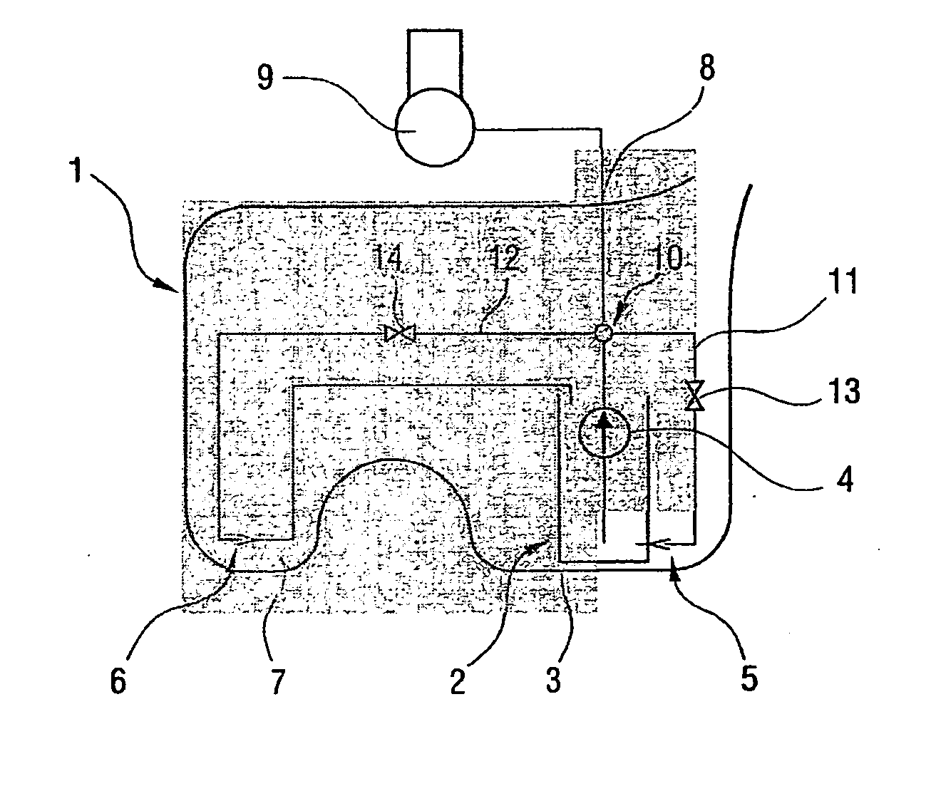
[0018]FIG. 1 shows a fuel tank 1 in the form of a saddle tank for a motor vehicle having a fuel feed unit 2 arranged therein. The fuel feed unit 2 has a fuel pump 4, drawing in fuel from a swirl pot 3 arranged in the bottom area of the fuel tank 1, and two suction jet pumps 5, 6 for filling the swirl pot 3. One of the suction jet pumps 6 is arranged in a chamber 7 of the fuel tank 1 separated from the swirl pot 3, whilst the other suction jet pump 5 fills the swirl pot 3 with fuel directly surrounding the former. From the delivery side of the fuel pump 4 a feed line 8 leads to an internal combustion engine 9 of the motor vehicle. The fuel pump 4 is controlled as a function of the demand of the internal combustion engine 9.

[0019] A distributor 10, to which pump fluid lines 11, 12 leading to the suction jet pumps 5, 6 are connected, is arranged in the feed line 8. These pump fluid lines 11, 12 serve to supply the suction jet pumps 5, 6 with fuel as working fluid. Volume flow reducing...


PUM

PropertyMeasurementUnit
Pressureaaaaaaaaaa

Abstract

The invention relates to a fuel feed unit (2) for a motor vehicle, comprising a volume flow reducing valve (13, 14) that is mounted in a pump fluid line (11, 12) leading to a suction jet pump (5, 6). Said volume flow reducing valve (13, 14) reduces the fuel volume flow supplied to the suction jet pump (5, 6) when the feed pressure of the fuel pump (4) increases, thereby avoiding unnecessary feed of fuel to the suction jet pump (5, 6).

Description

BACKGROUND OF THE INVENTION [0001] The invention relates to a fuel feed unit for feeding fuel from a fuel tank, having a fuel pump drawing in fuel from a swirl pot, a suction jet pump feeding fuel from the fuel tank into the swirl pot, and a pump fluid line led to the suction jet pump from the delivery side of the fuel pump. [0002] Such fuel feed units are commonly used in modern motor vehicles and are known in practice. The suction jet pumps are supplied with fuel by the fuel pump and feed fuel from the fuel tank into a swirl pot of the fuel feed unit, for example. In the known feed units fuel is delivered irrespective of whether fuel is present in the swirl pot. [0003] The suction jet pump, particularly in demand-controlled feed units, in which the delivery capacity of the fuel pump is controlled as a function of the fuel demand of an internal combustion engine of the motor vehicle, is designed in such a way that it delivers sufficient fuel even in the event of a low delivery pres...

Claims


Application Information

Patent Timeline
IPC IPC(8): B01D47/02F02M37/04B60K15/077F02M37/02F02M37/10
CPCB60K15/077F02M37/106F02M37/025Y10T137/86075
Inventor DICKENSCHEID, LOTHAR
Owner SIEMENS AG
Why Eureka
Try Eureka