Apparatus, a system and a method for securing and/or for displaying a device on a fixture

US20070152819A1Inactive Publication Date: 2007-07-05SENNCO SOLUTIONS

Image

  • Apparatus, a system and a method for securing and/or for displaying a device on a fixture
  • Apparatus, a system and a method for securing and/or for displaying a device on a fixture
  • Apparatus, a system and a method for securing and/or for displaying a device on a fixture

Examples


Embodiment Construction

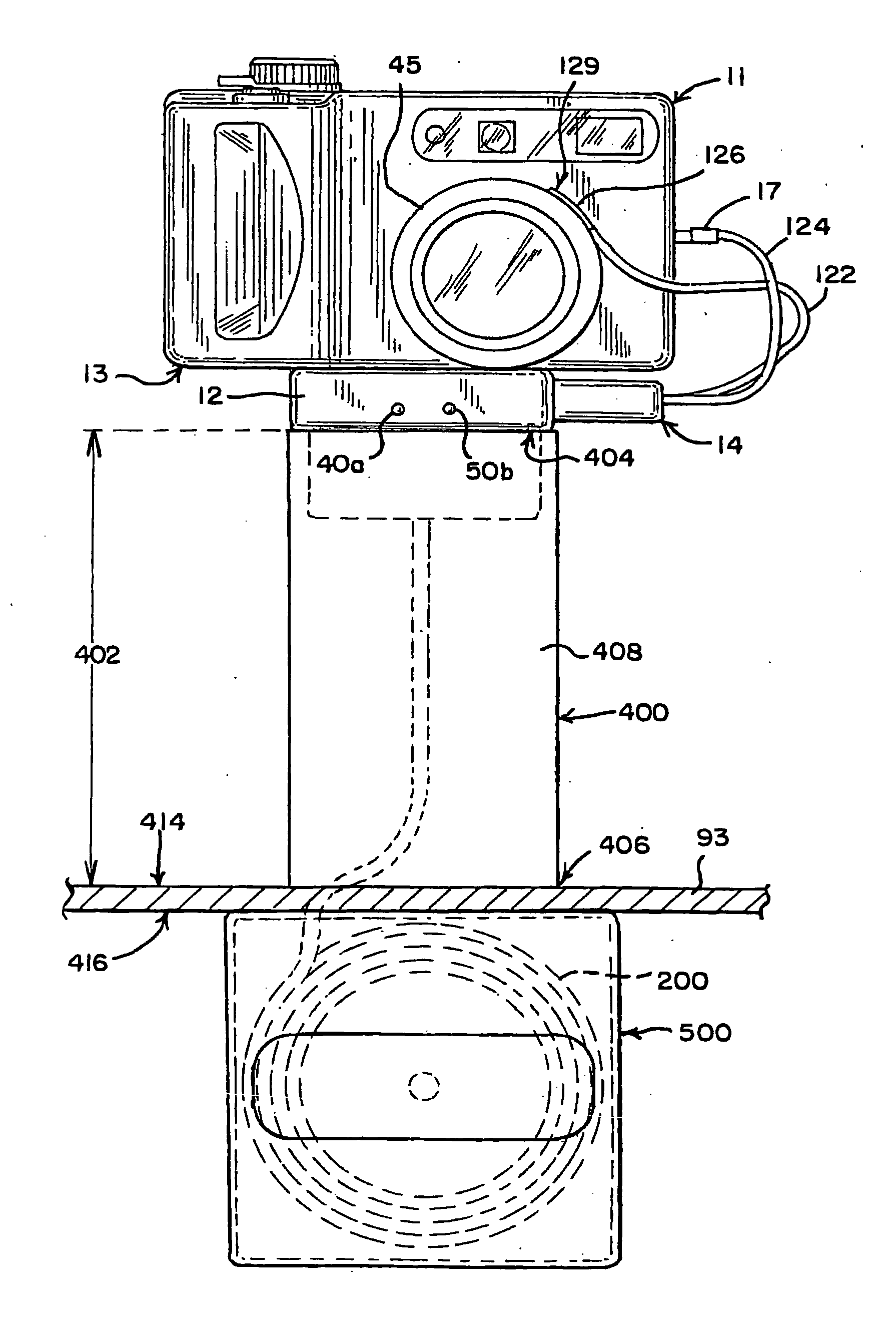
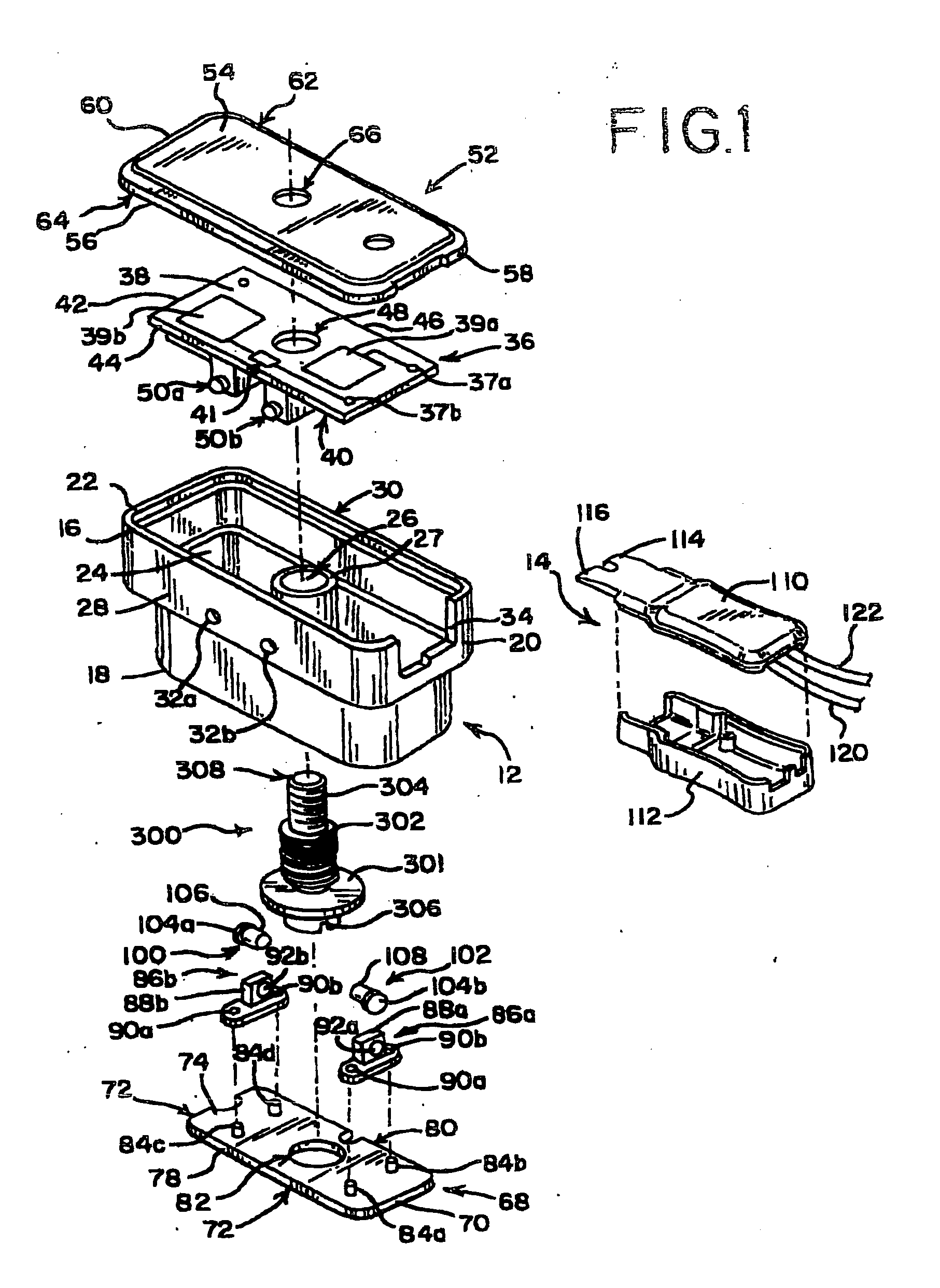
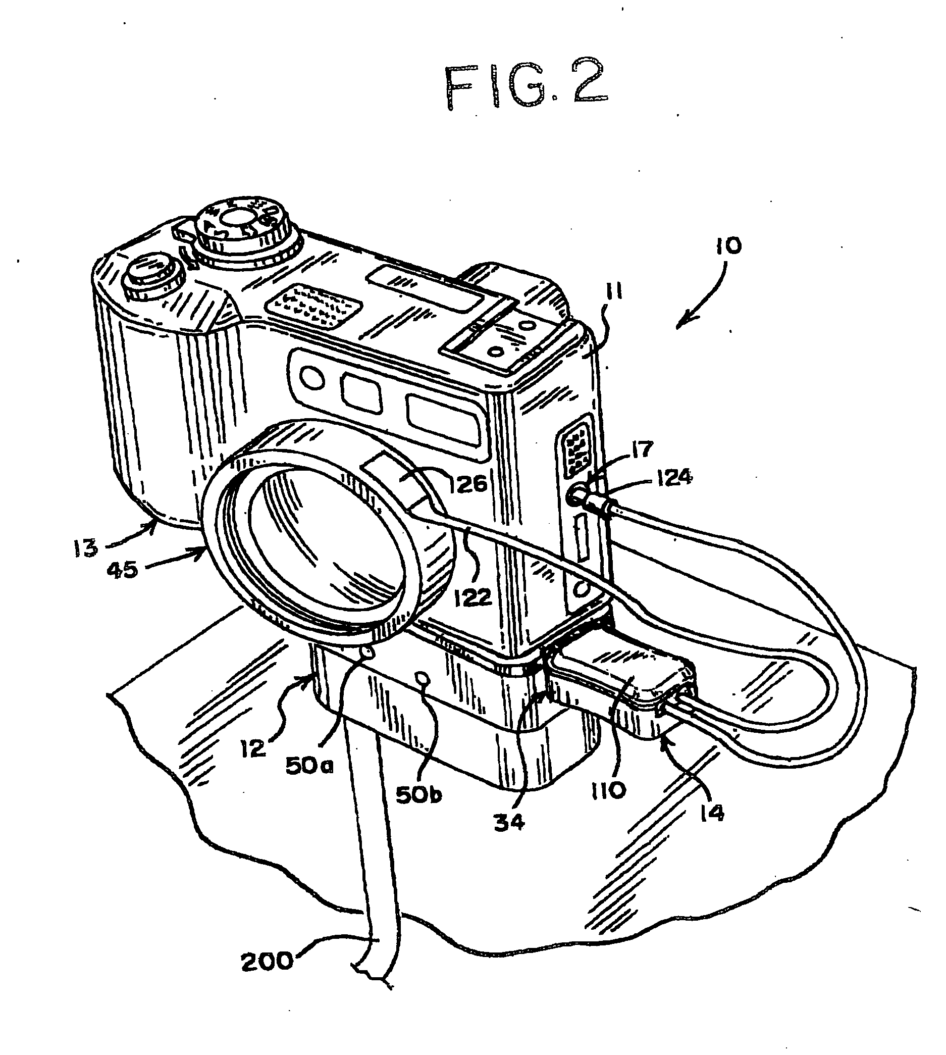
[0066] The present invention relates to an apparatus, a system and a method for securing and / or for displaying a device on a fixture. The apparatus, the system and the method for securing and / or for displaying a device on a fixture may attach and / or may secure the device and / or a detachable element of the device to a fixture. A housing and / or a cable may connect the device and / or the detachable element to the fixture. The housing may have an optical sensor and / or a sensor board with a micro-controller and / or a resistor in communication with the micro-controller. An alarm box and / or an alarm board may be in communication with an optical sensor and / or the micro-controller via a cable. A power source may be in communication with the micro-controller via the cable to control a voltage which may be delivered from the power source to the device. Furthermore, the cable may extend outward with respect to a base, a retracting means and / or the fixture which may allow the device and / or the det...


PUM


Abstract

An apparatus, a system and a method secure and / or display a device on a fixture. Additionally, the apparatus, the system and the method attach and / or secure the device and / or a detachable means of the device to the fixture. A housing and / or a cable connects the device and / or the detachable means of the device to an alarm box and / or an alarm board. The housing has an optical sensor and / or a sensor board with a micro-controller and / or a resistor in communication with the micro-controller. The alarm box and / or the alarm board is in communication with an optical sensor and / or the micro-controller via a cable. A power source is in communication with the micro-controller via the cable to control a voltage which delivers from the power source to the device. Furthermore, the cable extends outward with respect to the fixture and / or a retracting means which allows the device and / or the detachable element of the device to be manipulated and / or to be examined by a customer and / or a user.

Description

BACKGROUND OF THE INVENTION [0001] The present invention generally relates to an apparatus, a system and a method for securing and / or for displaying a device on a fixture. More specifically, the present invention relates to an apparatus, a system and a method for securing and / or for displaying a portable electronic device, such as, for example, a camera, a camcorder, a digital camera, a digital music player, a video game, a digital video player, a digital video recorder, a personal data assistant (hereinafter “a PDA”), a cellular telephone and / or the like. The apparatus, the system and the method for securing and / or for displaying the device on the fixture may be utilized to prevent theft of and / or destruction of the device. The device may be a portable electronic device which may be, for example, displayed for sale by a retailer, a wholesaler and / or the like. [0002] The apparatus, the system and the method for securing and / or for displaying the device on the fixture may have a hous...

Claims


Application Information

Patent Timeline
05 Jul 2007
Publication
US20070152819A1
IPC
G08B13/14; G08B21/00
CPC
G08B13/1409; G08B13/1481; G08B13/1445
Inventors
MARSZALEK, CHRISTOPHER; HORVATH, DANIEL