Vehicle-mounted electronic device

a technology for electronic devices and mounting structures, which is applied in the direction of dashboard fitting arrangements, machine supports, instruments, etc., can solve the problems of difficult manipulation and difficulty in device manipulation, and achieve the effect of increasing the size of the operation panel

Inactive Publication Date: 2005-01-06
KENWOOD CO LTD
View PDF8 Cites 42 Cited by
  • Summary
  • Abstract
  • Description
  • Claims
  • Application Information

AI Technical Summary

Benefits of technology

[0013] The present invention has been made in view of these points. A second objective of the invention is to provide a vehicle-mounted electronic device capable of increasing the sizes of

Problems solved by technology

The space for the display panel and operation keys of the operation panel 34 therefore becomes smaller so that the device manipulation becomes difficult.
However, since the operation panel 34 is requir

Method used


Image

  • Vehicle-mounted electronic device
  • Vehicle-mounted electronic device
  • Vehicle-mounted electronic device

Examples


first embodiment

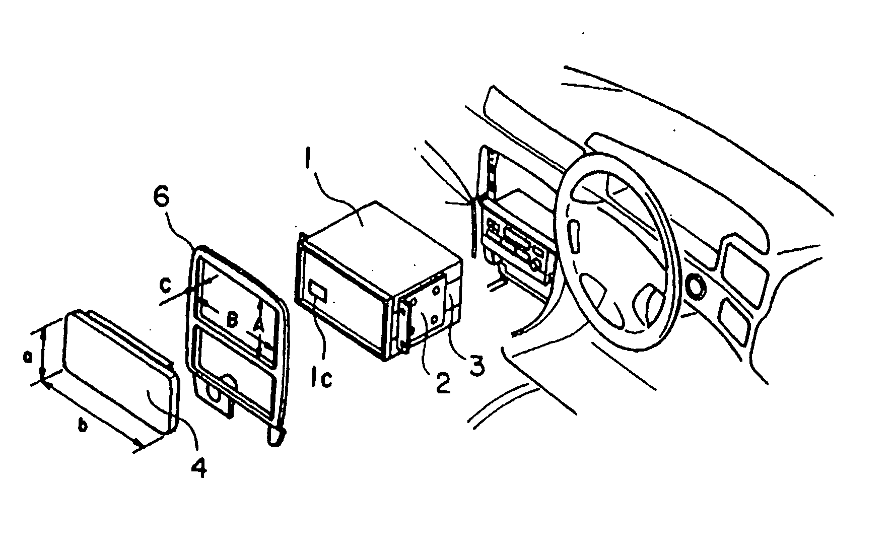
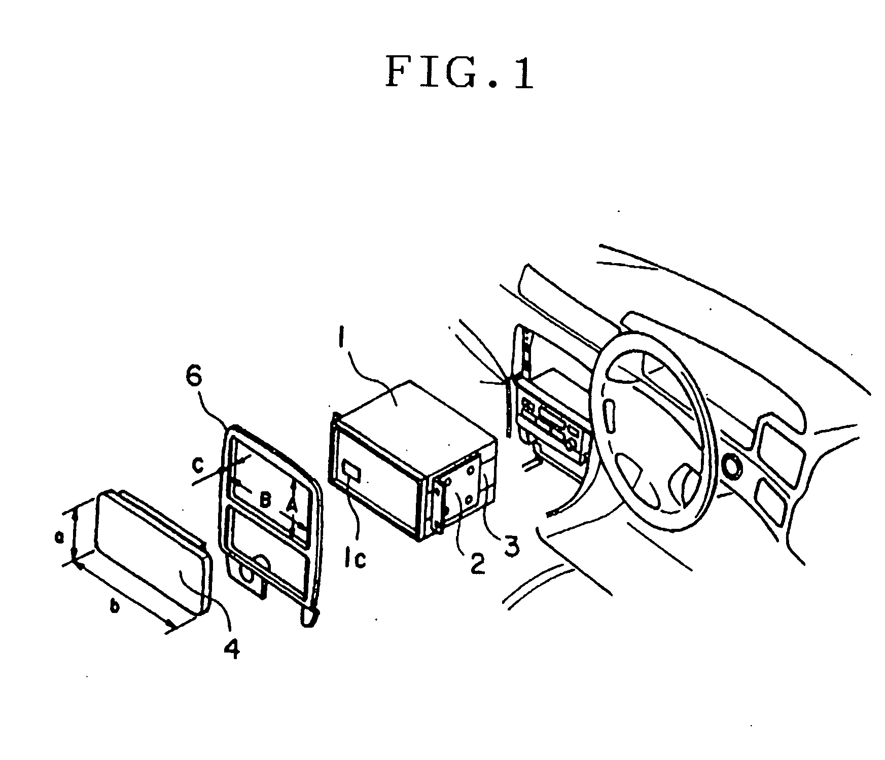
[0039] With reference to the accompanying drawings, the mount structure for mounting a vehicle-mounted electronic device according to the embodiments of the first invention will be described. FIG. 1 is a schematic broken perspective view of the mount structure for mounting a vehicle-mounted electronic device according to the first invention. FIG. 2 is a partial broken perspective view showing the mount structure for mounting the vehicle-mounted electronic device shown in FIG. 1.

[0040] As shown in FIGS. 1 and 2, a subsidiary bracket 3 is mounted on an electronic device main body chassis 1 with screws, and a mounting bracket 2 is mounted on the subsidiary bracket 3 with screws. As the mounting bracket 2 is mounted on the vehicle, the electronic device main body chassis 1 is fixed to the vehicle.

[0041] Thereafter, a cluster panel 6 is fixed to the vehicle, surrounding the periphery of the electronic device main body, and a panel 4 is mounted on the electronic device main body via the ...

second embodiment

[0046] FIGS. 3(a) is a broken perspective view partially showing the mount structure for mounting a vehicle-mounted electronic device according to the first invention, FIG. 3(b) is an enlarged perspective view showing a subsidiary bracket 7 used for the mount structure shown in FIG. 3(a). In this example, the subsidiary bracket 7 is fixed to the electronic device main body chassis 1 with screws 5 which are inserted into E-character shaped holes 7a formed through the sub-sidiary bracket 7. Screws 5 inserted into the holes of the mounting bracket 2 are threaded into tapped holes 7b of the subsidiary bracket 7, so that the mounting bracket 2 is fixed to the subsidiary bracket 7.

[0047] By changing the position of the screw 5 in the E-character shaped hole 7a, the position and height along a depth direction of the subsidiary bracket 7 relative to the electronic device main body chassis 1 can be adjusted. The other structures are similar to those of the first embodiment.

[0048]FIG. 4 is a...


PUM


Abstract

The invention provides a structure for attaching the main body and components of a vehicle-mounted electronic device, capable of increasing the size of an operation panel and a monitor for the electronic device stored in a vehicle-mounted electronic device storage section. In a first phase of the invention, in a structure for attaching a vehicle-mounted electronic device by fixing a vehicle-mounted electronic device to a vehicle, fixing a cluster panel to the vehicle in such a manner as to pass the vehicle-mounted electronic device therethrough, and fixing a panel wider than the opening in the cluster panel to the vehicle-mounted electronic device in such a manner as to place it over the cluster panel, a sub-bracket is attached to the lateral surface of the electronic device main body in such a manner that its position can be adjusted, and an attaching metal element is fastened to the sub-bracket so as to fasten the attaching metal element to the vehicle.

Description

BACKGROUND OF THE INVENTION [0001] 1. Field of the Invention [0002] The present invention relates to the mount structure for mounting a vehicle-mounted electronic device, and more particularly to the mount structure suitable for mounting the main body of a vehicle-mounted electronic device having a large panel and to the mount structure for mounting an operation panel and a monitor of a vehicle-mounted electronic device. [0003] 2. Related Background Art [0004] As shown in FIG. 13, when a vehicle-mounted electronic device such as a car stereo equipment is mounted on a housing recess of a vehicle, a mounting bracket 15 is mounted on an electronic device main body chassis 32 with screws, to mount the mounting bracket 15 on a vehicle. A cluster panel 31 is mounted covering the front side of the electronic device, and a panel 34 disposed on the front side of the electronic device main body is protruded from an opening of the cluster panel 31. [0005]FIG. 4 shows an example of the panel 34...

Claims


Application Information

Patent Timeline
IPC IPC(8): B60R11/00B60R11/02
CPCB60K37/06B60K2350/941B60R11/0211B60R2011/027B60R2011/0047B60R2011/0052B60R2011/0094B60R2011/0005B60K2370/81
Inventor MATSUDA, AKIHIROHIRAKO, RYOICHI
Owner KENWOOD CO LTD
Why Eureka
Try Eureka