Head and neck immobilization in magnetic resonance imaging

a magnetic resonance imaging and head and neck technology, applied in the field of magnetic resonance imaging systems, apparatuses and, can solve the problems of limiting the imaging information obtained, providing a claustrophobic environment for patients, and affecting the comfort level of patients

Active Publication Date: 2010-04-27
FONAR
View PDF22 Cites 46 Cited by
  • Summary
  • Abstract
  • Description
  • Claims
  • Application Information

AI Technical Summary

Benefits of technology

[0014]Further in accordance with this embodiment, the at least one positioning member comprises a rod member having a flattened portion that terminates a substantially circular portion. When the flattened portion of the rod member is adjacent to the retainer the rod is free to move and when the rod member circular portion is adjacent the retainer the rod is held in place.
[0015]Another aspect of the present invention is a system for magnetic resonance imaging comprisin

Problems solved by technology

Also, magnetic resonance imaging can obtain images of soft tissues and other features within the body which are not readily visualized using other imaging techniques.
Moreover, equipment of this type provides a claustrophobic environment for the patient.
This affects the conditions under which imaging may be performed and also affects the comfort level of the patient.
The position of a patient during magnetic resonance imaging may affect or limit the imaging information obtained.
A

Method used


Image

  • Head and neck immobilization in magnetic resonance imaging
  • Head and neck immobilization in magnetic resonance imaging
  • Head and neck immobilization in magnetic resonance imaging

Examples


Embodiment Construction

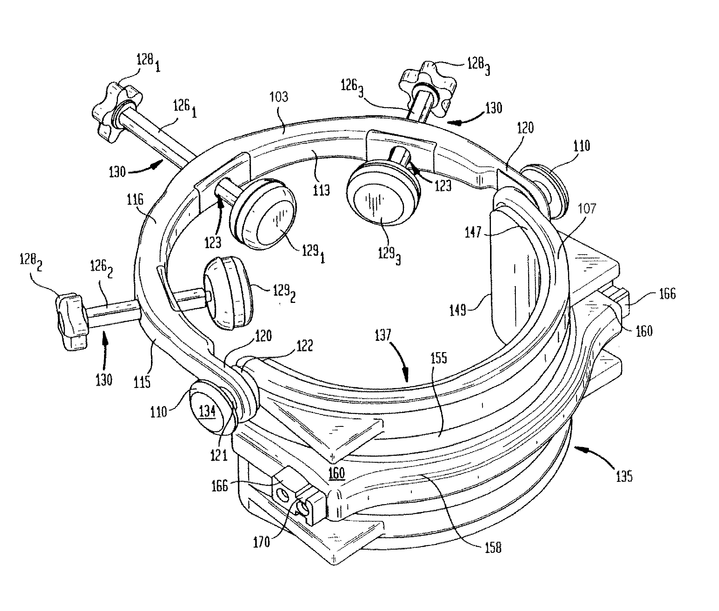
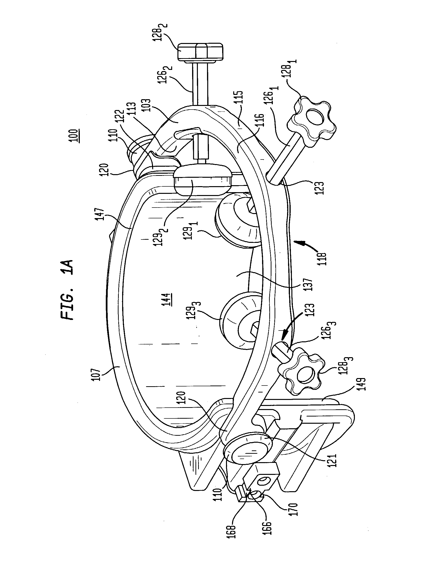
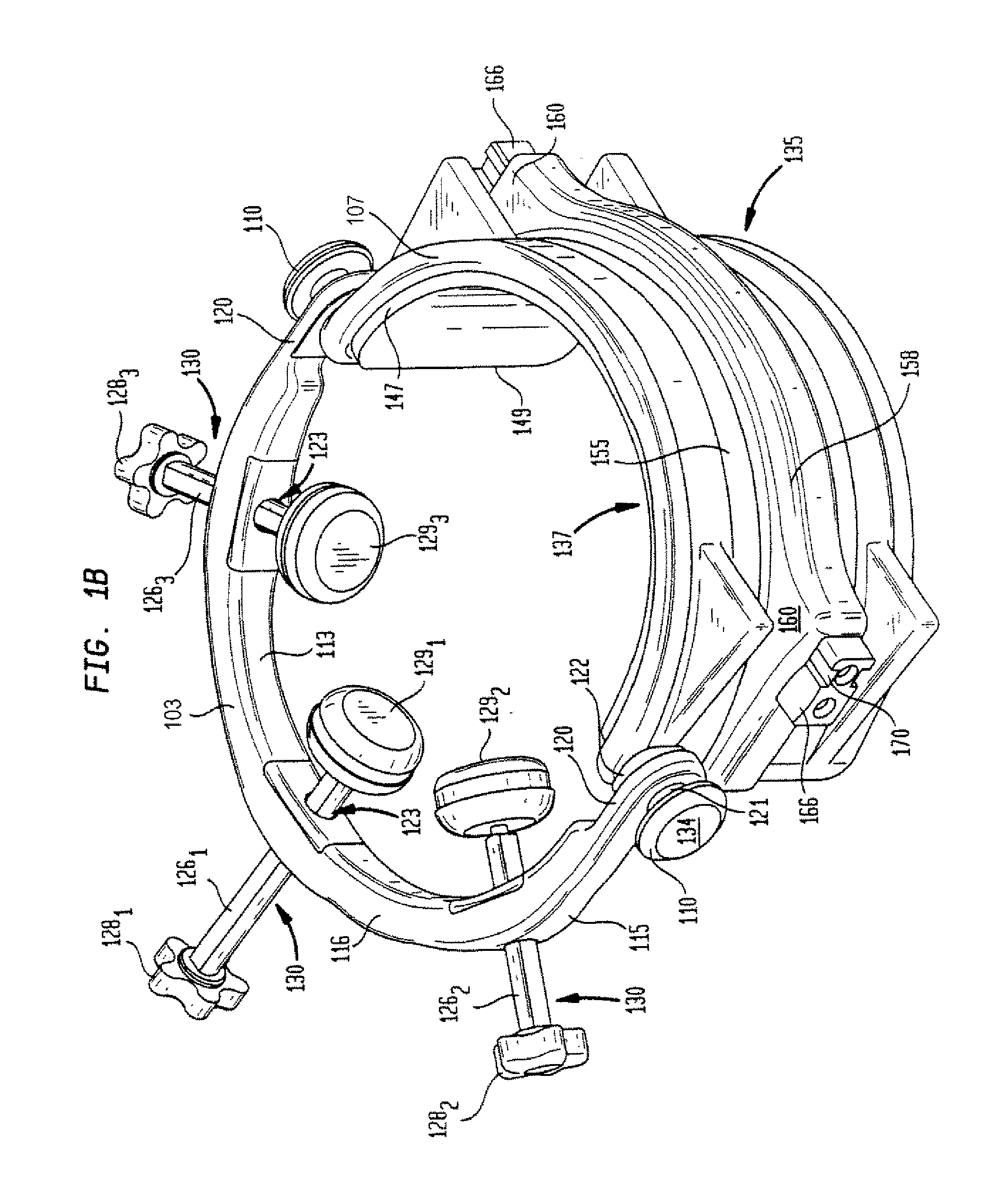
[0027]An aspect of the present invention is a head and neck immobilization device or halo 100 as shown in FIG. 1, in which FIG. 1A and FIG. 1B show front and rear perspective views of the device 100, respectively. The device 100 comprises a first substantially C-shaped or arcuate member 103 and a second C-shaped or arcuate member 107. The first and second C-shaped members 103 and 107 are mounted to each other by pivot mechanism 110. Pivot mechanism 110 advantageously allow first C-shaped member 103 to pivot about second C-shaped member 107 or vice-versa.

[0028]The first C-shaped member 103 includes an inner side wall 113 and an outer side wall 115. The inner side wall 113 defines an inner surface. The outer side wall 115 similarly defines an outer surface. The inner and outer side walls 113, 115 are terminated at an end by upper lateral wall 116 and at another end by lower lateral wall 118. In a preferred embodiment, the edges at the intersection of side walls 113, 115 and lateral wa...


PUM


Abstract

Apparatus, system and method for immobilizing a patient's head during imaging. The apparatus includes two substantially C-shaped members that are pivotably mounted to each other. One C-shaped member includes at least one adjustable positioning rod for securing the patient's head during imaging. The apparatus is attached to a magnet resonance imaging apparatus to form a system. The system is used for imaging a patient whose head and neck is immobilized by the apparatus.

Description

BACKGROUND OF THE INVENTION[0001]The present invention relates to magnetic resonance imaging systems, apparatus and procedures. In magnetic resonance imaging, an object to be imaged as, for example, a body of a human subject, is exposed to a strong, substantially constant static magnetic field. The static magnetic field causes the spin vectors of certain atomic nuclei within the body to randomly rotate or “precess” around an axis parallel to the direction of the static magnetic field. Radio frequency excitation energy is applied to the body, and this energy causes the precessing automatic nuclei to rotate or “precess” in phase and in an excited state. As the precessing atomic nuclei relax, weak radio frequency signals are emitted; such radio frequency signals are referred to herein as magnetic resonance signals.[0002]Different tissues produce different signal characteristics. Furthermore, relaxation times are the dominant factor in determining signal strength. In addition, tissues h...

Claims


Application Information

Patent Timeline
IPC IPC(8): A61B5/05
CPCA61B5/0555G01R33/3806A61G13/121A61B5/055
Inventor GREEN, CHARLES A.VOTRUBA, JANWAHL, WILLIAM H.CINOGLU, ARTO
Owner FONAR
Why Eureka
Try Eureka