

Power transmission device, power transmission method, power reception device, power reception method, and power transmission system
a technology of power transmission device and power reception device, which is applied in the direction of battery data exchange, exchanging data charger, inductance, etc., can solve the problem of difficult to transmit power in a stable manner
- Summary
- Abstract
- Description
- Claims
- Application Information
AI Technical Summary
Benefits of technology
Problems solved by technology
Method used
Image


Examples
first embodiment
2. First Embodiment
[0073]The inventor of the present invention invents a technique for changing the resonant frequency based on the basic power transmission technique. Here, such a technique is referred to as a resonant frequency variation technique. Among power transmission systems to which embodiments of the present invention are applied, an embodiment to which such a resonant frequency variation technique is applied is a first embodiment.
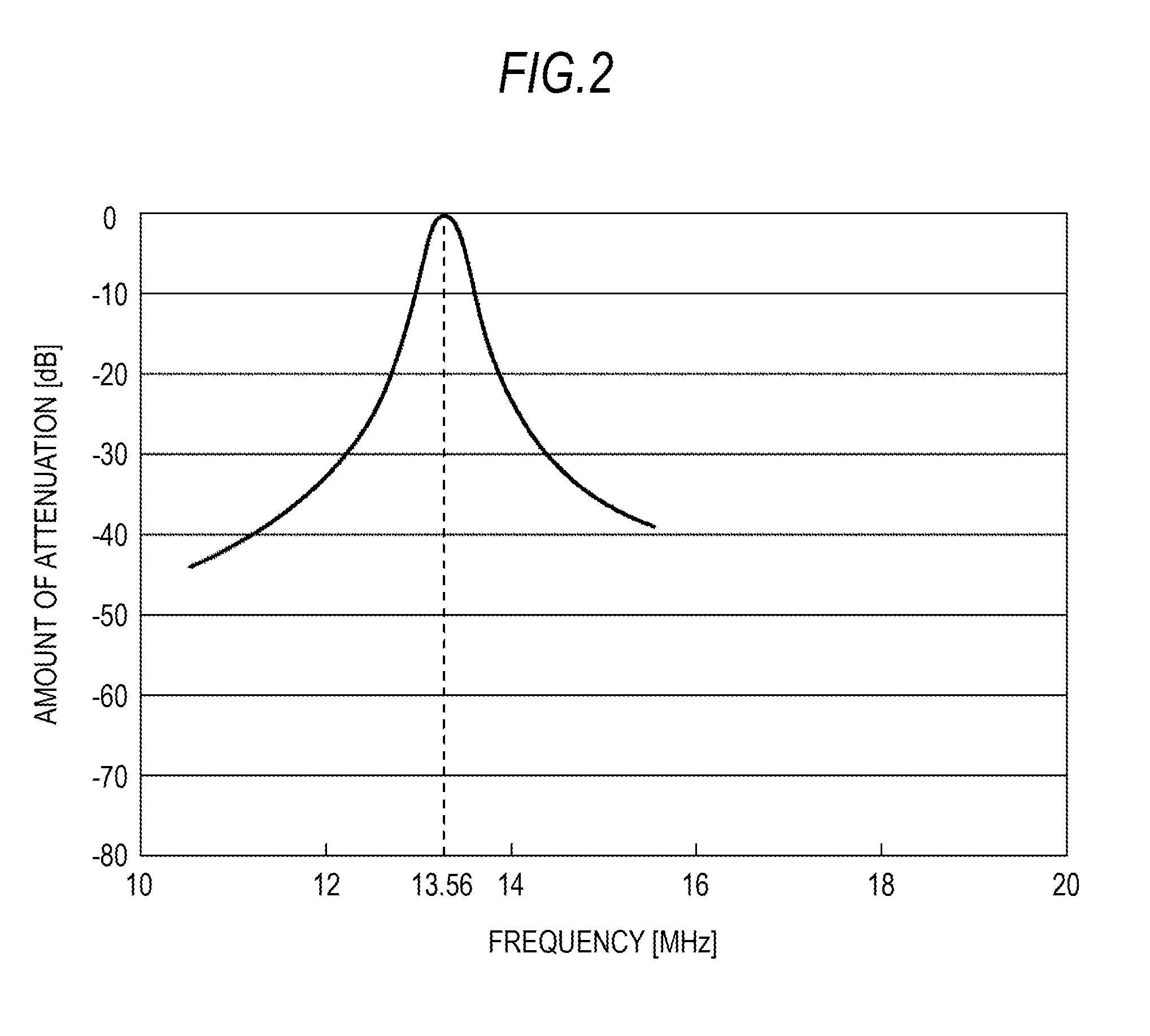
[0074]In other words, the resonant frequency variation technique is applied to the first embodiment, so that the resonant frequency is controlled to coincide with the oscillation frequency even in the middle of use of the power transmission system. As a result, a decrease in the transmission efficiency can be prevented. In other words, the power can be stably transmitted in a non-contact manner.
[0075]Hereinafter, the first embodiment will be further described in detail.
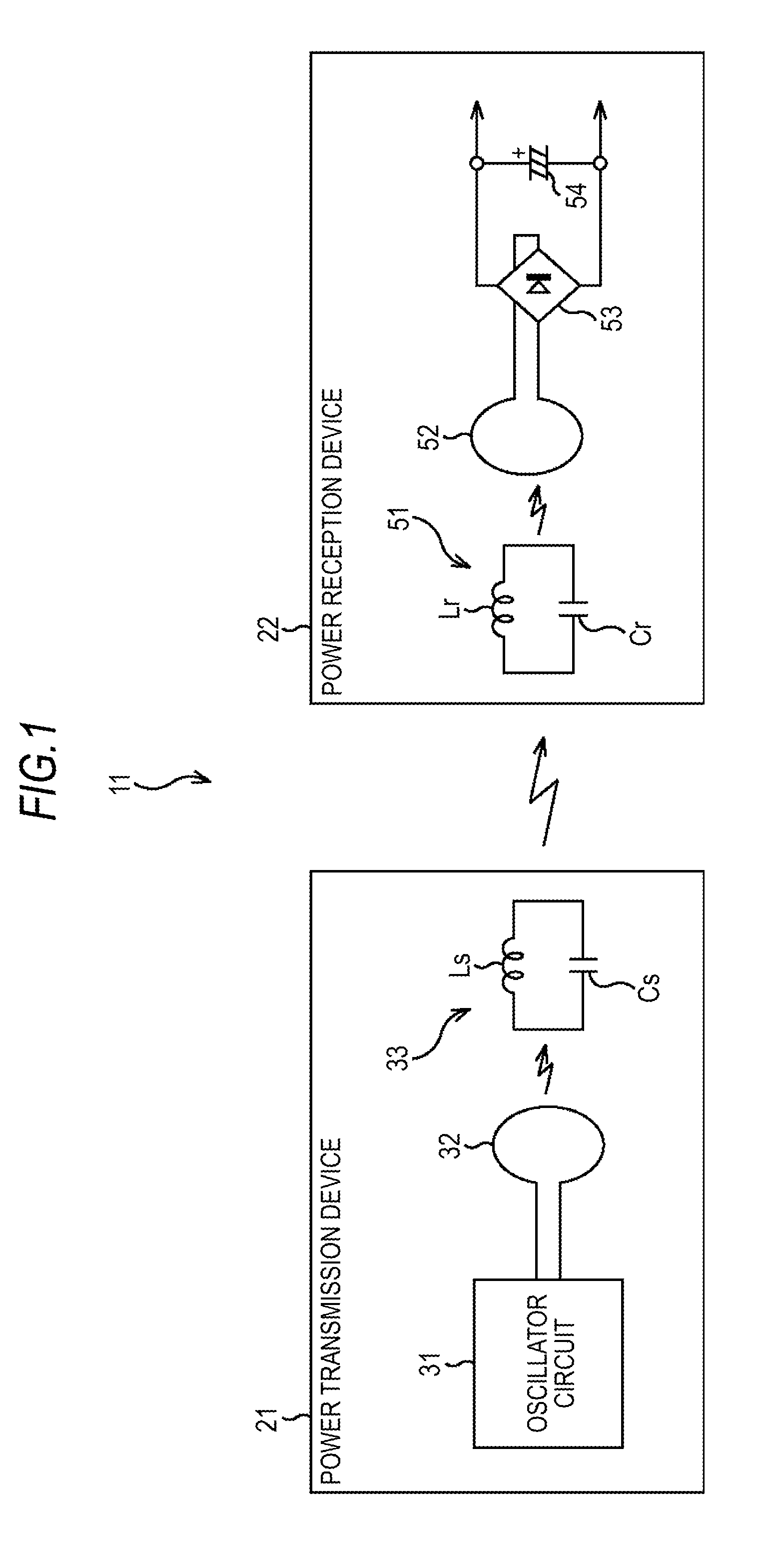
Configuration Example of Power Transmission System According to First Embodime...
second embodiment
3. Second Embodiment
[0136]Furthermore, in the view point of maximizing the transmission efficiency, that is, in the view point of maximizing the reception power P, any control process for allowing the resonant frequencies and the oscillation frequency to coincide with each other may be performed.
[0137]In other words, according to the first embodiment, the reception-side resonant frequency variation control and the transmission-side resonant frequency variation control are employed as the control process for allowing the resonant frequencies and the oscillation frequency f31 to coincide with each other by fixing the oscillation frequency and changing the resonant frequencies.
[0138]However, in the viewpoint of maximizing the reception power P, a control process that allows the resonant frequencies and the oscillation frequency to coincide with each other by fixing the resonant frequencies and changing the oscillation frequency may be performed. Hereinafter, such a control process is r...
third embodiment
4. Third Embodiment
[0164]In the above-described first and second embodiments, a distance (hereinafter, referred to as a transmission distance) between the transmission side and the reception side is fixed. However, for example, when the power reception device is configured by a cellular phone or the like and can be freely carried or the like, there are cases where the transmission distance is changed.
[0165]In such a case, the reception power P changes in inverse proportion to the transmission distance. Thus, in a case where any countermeasure is not performed for the case where the transmission distance varies, for example, when the transmission distance is short, the reception power P is equal to or greater than the power (hereinafter, referred to as a necessary power) that may be needed on the reception side. Accordingly, unnecessary radiation is increased, or unnecessary power may be consumed. On the other hand, when the transmission distance is long, the reception power P is les...
PUM
 Abstract
Description
Claims
Application Information