
Systems and methods for detecting and protecting a wireless power communication device in a wireless power system

a wireless power communication and wireless power technology, applied in the field of wireless power, can solve the problems of increasing the power consumption of battery-powered electronic devices, increasing the power consumption of devices, and sometimes inconvenient or cumbersome cables and similar connectors, and achieve the effect of reducing the power level of the wireless power transfer field

Active Publication Date: 2012-10-04
QUALCOMM INC
View PDF2 Cites 330 Cited by
  • Summary
  • Abstract
  • Description
  • Claims
  • Application Information

AI Technical Summary

Benefits of technology

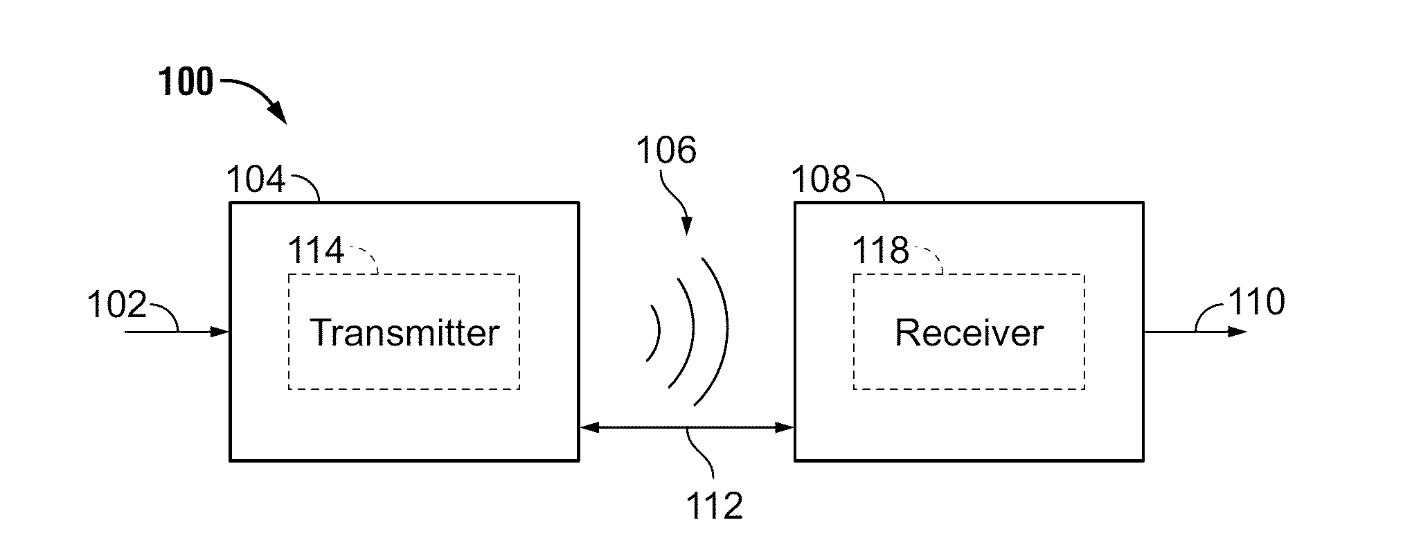
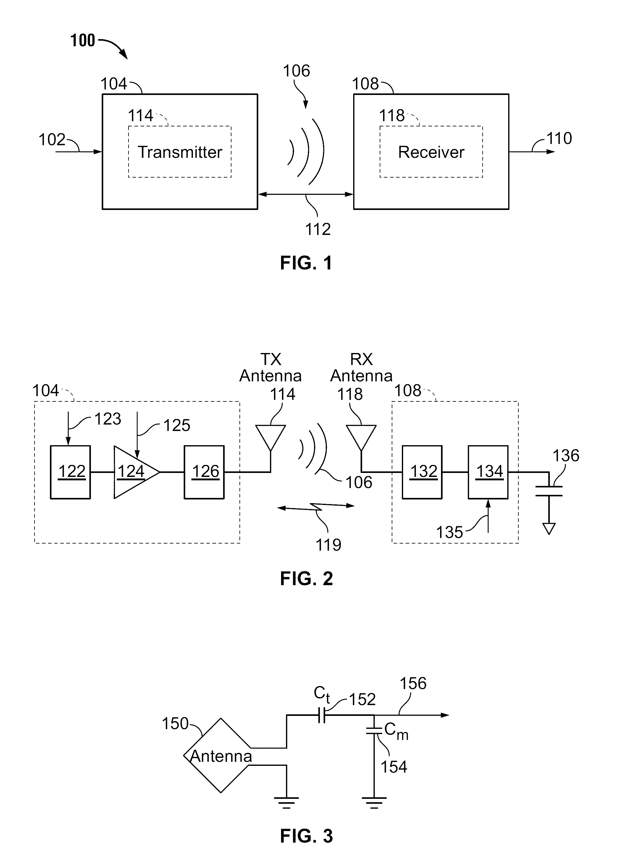
The patent describes a system and method for detecting a communication device in a wireless power transfer region. The system generates a wireless power transfer field and transmits two signals at different frequencies. The system detects a third signal that is an intermodulation product of the two signals. When the third signal is detected, the system reduces the power level of the wireless power transfer field to avoid interference with the communication device. The technical effect of this invention is to improve the efficiency and reliability of wireless power transfer by detecting and reducing intermodulation products, which can improve the quality of wireless communication.

Problems solved by technology

While battery technology has improved, battery-powered electronic devices increasingly require and consume greater amounts of power.
As such, these devices constantly require recharging.
Cables and similar connectors may sometimes be inconvenient or cumbersome and have other drawbacks.
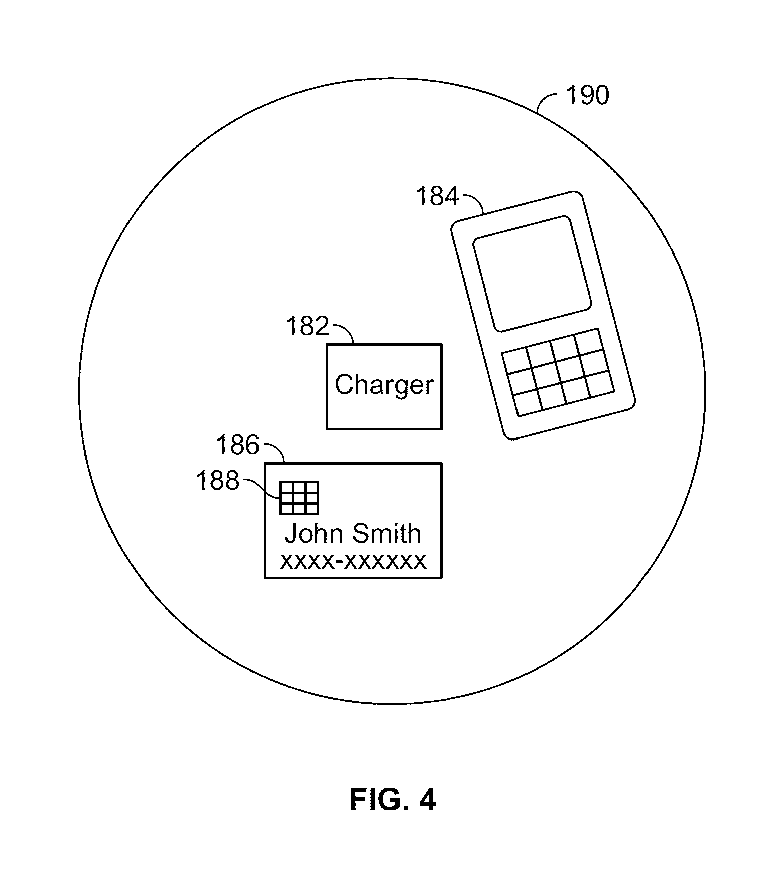
A vulnerable device, such as a near field communication (NFC) device, which is operating at the same frequency or capable of receiving power from a wireless power transmitter, may receive excessive power from the wireless power transmitter.
Receiving excessive power may result in undesirable heating or destruction of the vulnerable device.

Method used


Image

  • Systems and methods for detecting and protecting a wireless power communication device in a wireless power system
  • Systems and methods for detecting and protecting a wireless power communication device in a wireless power system
  • Systems and methods for detecting and protecting a wireless power communication device in a wireless power system

Examples


Embodiment Construction

[0024]The detailed description set forth below in connection with the appended drawings is intended as a description of embodiments of the present invention and is not intended to represent the only embodiments in which the present invention can be practiced. The term “exemplary” used throughout this description means “serving as an example, instance, or illustration,” and should not necessarily be construed as preferred or advantageous over other embodiments. The detailed description includes specific details for the purpose of providing a thorough understanding of the embodiments of the invention. It will be apparent to those skilled in the art that the embodiments of the invention may be practiced without these specific details. In some instances, well-known structures and devices are shown in block diagram form in order to avoid obscuring the novelty of the embodiments presented herein.

[0025]Wirelessly transferring power may refer to transferring any form of energy associated wi...


PUM


Abstract

Embodiments are directed to detecting and limiting power transfer to communication device, such as NFC and RFID cards. A method may include detecting one or more communication devices positioned within a wireless power transfer region of a wireless power transmitter. The method may further include limiting an amount of power transmitted by a transmitter in response to the detection.

Description

CROSS REFERENCE TO RELATED APPLICATIONS[0001]This application claims priority benefit under 35 U.S.C. §119(e) to U.S. Provisional Patent Application No. 61 / 470,380 entitled “NEAR FIELD COMMUNICATION CARDS DETECTION” filed on Mar. 31, 2011, the disclosure of which is hereby incorporated by reference in its entirety.FIELD[0002]The present invention relates generally to wireless power. More specifically, the disclosure is directed to systems, device, and methods for detecting a vulnerable device (e.g., a device that may be damaged by a wireless power transfer field), including near-field communication devices and radio-frequency identification (RFID) cards, within a charging region of a wireless power transmitter. Some embodiments relate to systems, devices, and methods for adjusting wireless power transfer and / or limiting wireless power delivery based on detection of vulnerable devices, including near-field communication devices, positioned within a charging region of a wireless power...

Claims


Application Information

Patent Timeline
Patent Type & Authority Applications(United States)
IPC IPC(8): H02J17/00
CPCH02J7/025H02J5/005H04B5/0037H02J17/00H02J50/40H02J50/80H02J7/00034H02J50/20H02J50/90H02J50/12H04B5/79H04B5/77
Inventor DRENNEN, WILLIAM ANTHONY
Owner QUALCOMM INC
Learn More