Sub-lethal, wireless projectile and accessories

a wireless projectile and wireless technology, applied in the field of sublethal, wireless projectiles, can solve the problems of affecting innocent bystanders, 614 patents failing to address the effect of projectile glancing off of a target or otherwise, and determining the effectiveness of electrical shock in disabling any target individual, etc., to achieve the effect of reducing power levels (voltage), and reducing the total energy level

Inactive Publication Date: 2005-04-19
CSA ENERGY
View PDF20 Cites 80 Cited by
  • Summary
  • Abstract
  • Description
  • Claims
  • Application Information

AI Technical Summary

Benefits of technology

[0020]Amperage, power, pulse frequency, and lastly, voltage determine the effectiveness of electrical shock in disabling any target individual. A disabling, sub-lethal electrical shock does not require a high total energy level. Shocks in the range of 5 to 30 watts are generally disabling when the power is pulsed at rates of from 2 to 40 discharges per second, with rates around 20 being recognized as effective. For reasonable effectiveness, two or more pulsed discharges of 3 to 15 seconds are recommended. Long wavelength electricity 40 to 80 Hz is the most effect. Serious damage to the heart can result from shocks with power delivered at 60 Hz. When the power is delivered below the surface of the skin, for example by using electrodes that penetrate the skin and remain embedded, as a result of the previously noted low resistance of the subdural tissue, potential in the range of 100 to 350 volts is adequate to generate a disabling shock. Thus, electrical shocking devices that are specifically designed to penetrate the skin require significantly lower power levels (voltage) than those designed to discharge at the skin's surface or through clothing. High voltage tends to cause more immediate pain and tissue damage due to the heat generated by the voltage; thus, even for a sub-lethal or non-lethal device, penetrating the skin may be viewed as preferable to high voltage injuries to target individuals.
[0021]The low frequency (long wavelength) disabling shock can be combined as a carrier frequency with high frequency (short wave length) power. The combination reduces the more serious effects of the low frequency discharge on the heart. ?In addition, high frequency power has a more specific effect on disabling the central nervous system.

Problems solved by technology

Electrical devices have been used for such purposes with limited effectiveness.
The '614 patent fails to address the effect of the projectile glancing off of a target or otherwise failing to discharge the stunning material in an effective concentration in proximity to the target, or the impact on innocent by-standers.
In addition the device or weapon is limited to a single shot because the projectile must remain wired to the power-source weapon.

Method used


Image

  • Sub-lethal, wireless projectile and accessories
  • Sub-lethal, wireless projectile and accessories
  • Sub-lethal, wireless projectile and accessories

Examples


example 1

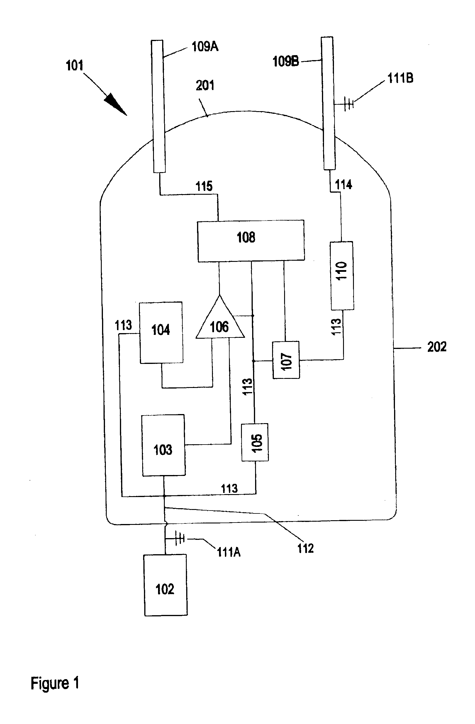
[0030]FIG. 1 illustrates the shock delivery circuit 101 and comprises at least nine basic components. The external basic DC power source 102 capable of supplying a power potential of from 3 to 15 DC volts powers the circuit but is physically separated from it and therefore not considered to be part of the circuit as the circuit ultimately functions in a wireless projectile; (1) a first oscillator 103 capable of creating a frequency of from 15 to 50 Hz; (2) a second oscillator 104 capable of creating a frequency of from 250 to 500 kHz; (3) a capacitor 105 capable of storing and discharging electrical energy to provide three or more discharges of eight or more seconds delivering a pulsating shock of from 5 to 30 watts with non-discharge periods of up to 3 seconds between the discharges; (4) a control and amplifying unit 106 capable of combining the frequencies delivered by the first oscillator 103 and the second oscillator 104 and of stepping-up the potential of the electrical energy ...

example 2

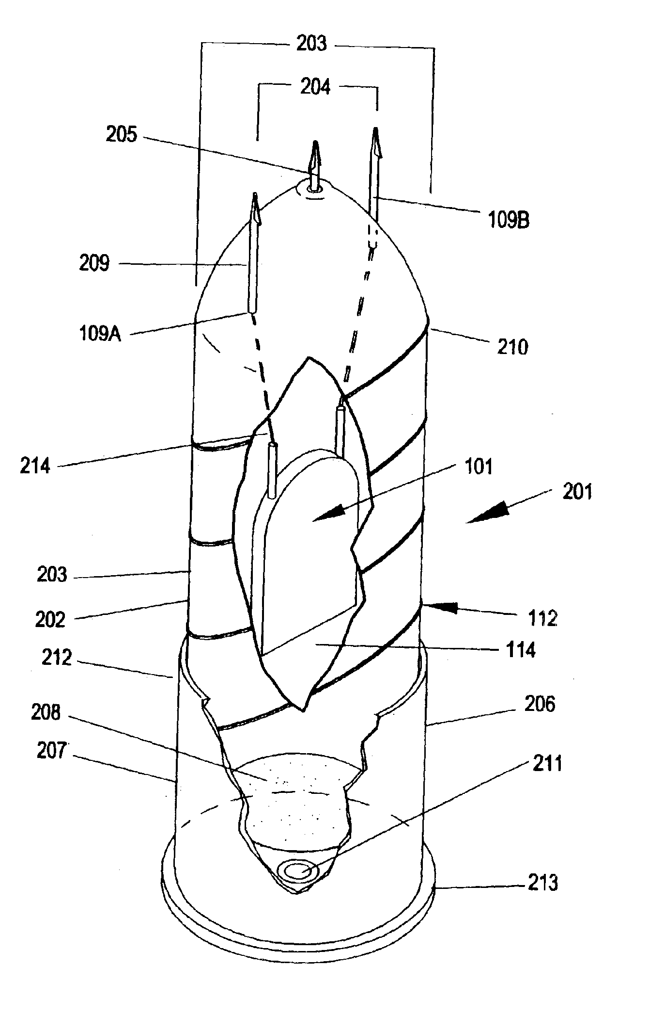
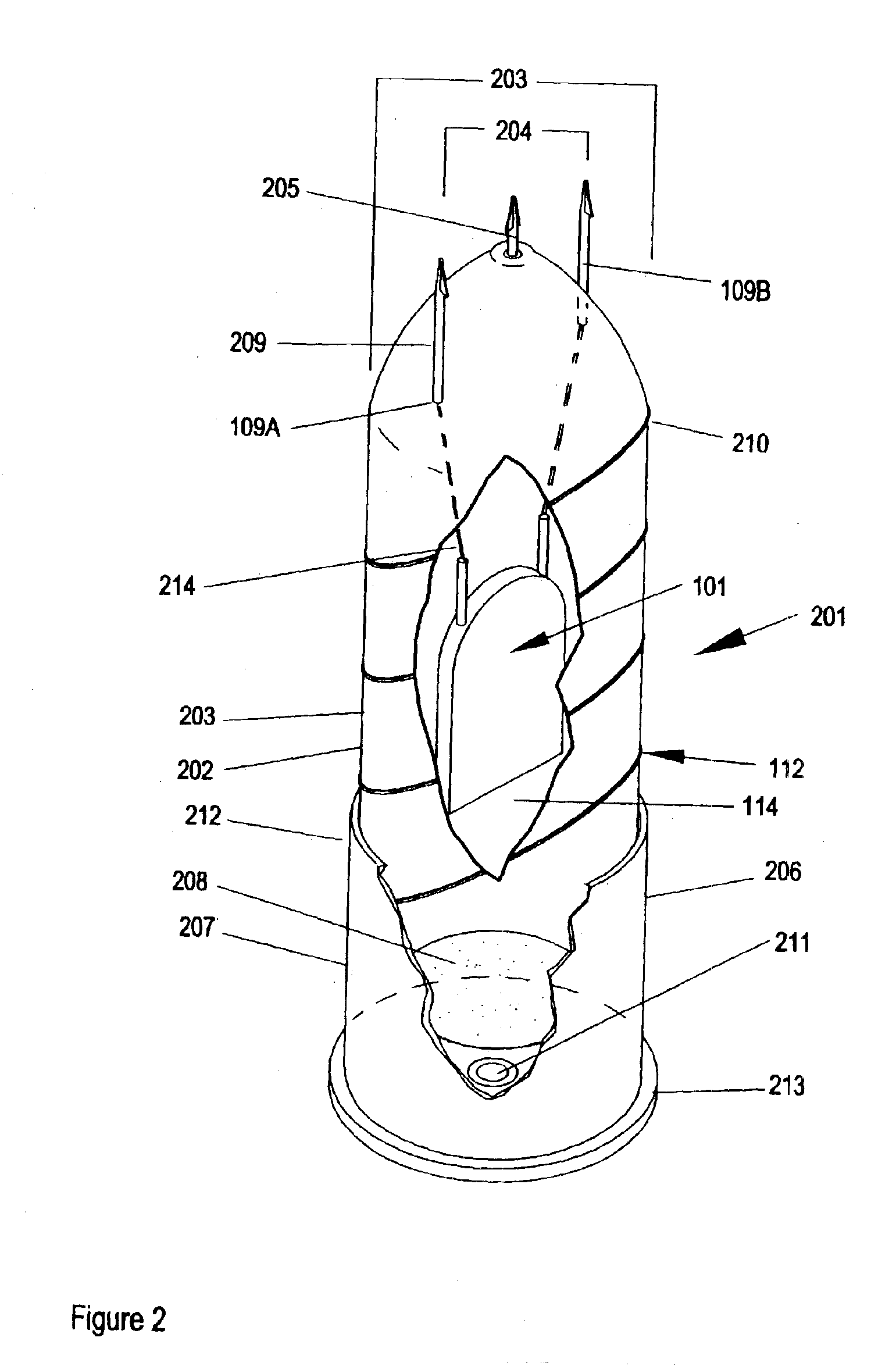
[0032]An embodiment of the invention illustrated in FIG. 2 anticipates delivery of the electrical circuit capable of delivering a disabling electrical shock by means of a projectile 201 capable of being at least partially inserted into a casing 206 in the manner comparable to the manner in which a bullet is seated in the casing for ammunition commonly used with fire arms. The distal end 208 of the projectile is inserted into the proximal end 212 of the casing 206. The casing 206 has an explosive or combustion chamber 207 that holds a charge of gun powder or comparable explosive. Wading (not shown) may separate the distal end 208 of the projectile from direct contact with the explosive charge and serve to ensure proper combustion of the charge. The distil end 213 of the casing is adapted to receive a standard, center fire primers 211. The projectile 201 is fabricated from any of several materials, such as plastic, hard rubber. The projectile is adapted to allow the entire circuit 101...

example 3

[0035]An alternative embodiment of the invention is described in FIG. 3. A wireless projectile 300 is adapted for being discharged from a wide array of pneumatic and spring powered weapons with smooth bore barrels, or to be thrown by hand under certain conditions. Unlike the device of FIG. 2, the device of FIG. 3 does not include a cartridge and chamber for an explosive propellant. The profile of the device 300 is variously described as cigar-shaped, torpedo-like, or dart-like. The body 301 has a rounded proximal, or front end 304, with a tapering distal end 306. A plurality of fins, as illustrated, three fins 302A, 302B, and 302C, are fixed to the surface 301 of the distal end 306 of the body 301 of the projectile.

[0036]The body 308 of the projectile is fabricated from plastic or hard rubber, although as in the case for the projectile of FIG. 2, other materials may be used including certain ceramics and even paper materials. The core 307 of the projectile is adapted to support the ...


PUM


Abstract

The invention is a circuit capable of being positioned in a variety of wireless projectile and of delivering a series of pulsed electric discharges in two wave frequencies so as to stun and disable a target individual. The projectiles are adapted to be discharged from a different types of devices and powered by explosive, pneumatic, or manual means. At least one mode includes the ability to deliver a stunning physical blow in addition to the electric shock. The device is sub-lethal, but totally disabling in effects on a target individual.

Description

RELATED APPLICATIONS[0001]This application claims the benefit of U.S. Provisional Patent Application Ser. No. 60 / 391,456 filed Jun. 25, 2002, and which is incorporated herein by reference.FIELD OF THE INVENTION[0002]This invention is directed to sub-lethal, wireless projectiles capable of delivering a disabling electrical shock to a target individual under a variety of settings and conditions. More specifically it is directed to a circuit that can be positioned in a wireless projectile and can deliver a series of sub-lethal, pulsating, disabling electrical shocks. The circuit delivers energy in at least two different bands to disable by at least one of the following: target individual's natural reaction to pain, loss of muscular control of target individual, disorientation suffered by target individual, and loss of balance of target individual.BACKGROUND OF THE INVENTION[0003]Recent acts of terrorism in the United States have generated renewed interest in and increased demands for d...

Claims


Application Information

Patent Timeline
Patent Type & Authority Patents(United States)
IPC IPC(8): F42B12/36F42B12/02F41H13/00H05C1/00
CPCF41H13/0031F42B12/36H05C1/00F42B12/362Y10S119/908
Inventor CARMAN, BRENT G.
Owner CSA ENERGY
Why Eureka
Try Eureka