System and method for overvoltage protection

a protection circuit and overvoltage technology, applied in the direction of safety/protection circuits, dc circuits to reduce harmonics/ripples, instruments, etc., can solve problems such as damage to the circuit being protected

Inactive Publication Date: 2009-06-11
VISTEON GLOBAL TECH INC
View PDF14 Cites 24 Cited by
  • Summary
  • Abstract
  • Description
  • Claims
  • Application Information

AI Technical Summary

Benefits of technology

[0010]Other objects and advantages of the present invention will become apparent upon reading th...

Problems solved by technology

The resistance introduced by the combination of resistors prevents the voltag...

Method used


Image

  • System and method for overvoltage protection
  • System and method for overvoltage protection
  • System and method for overvoltage protection

Examples


Embodiment Construction

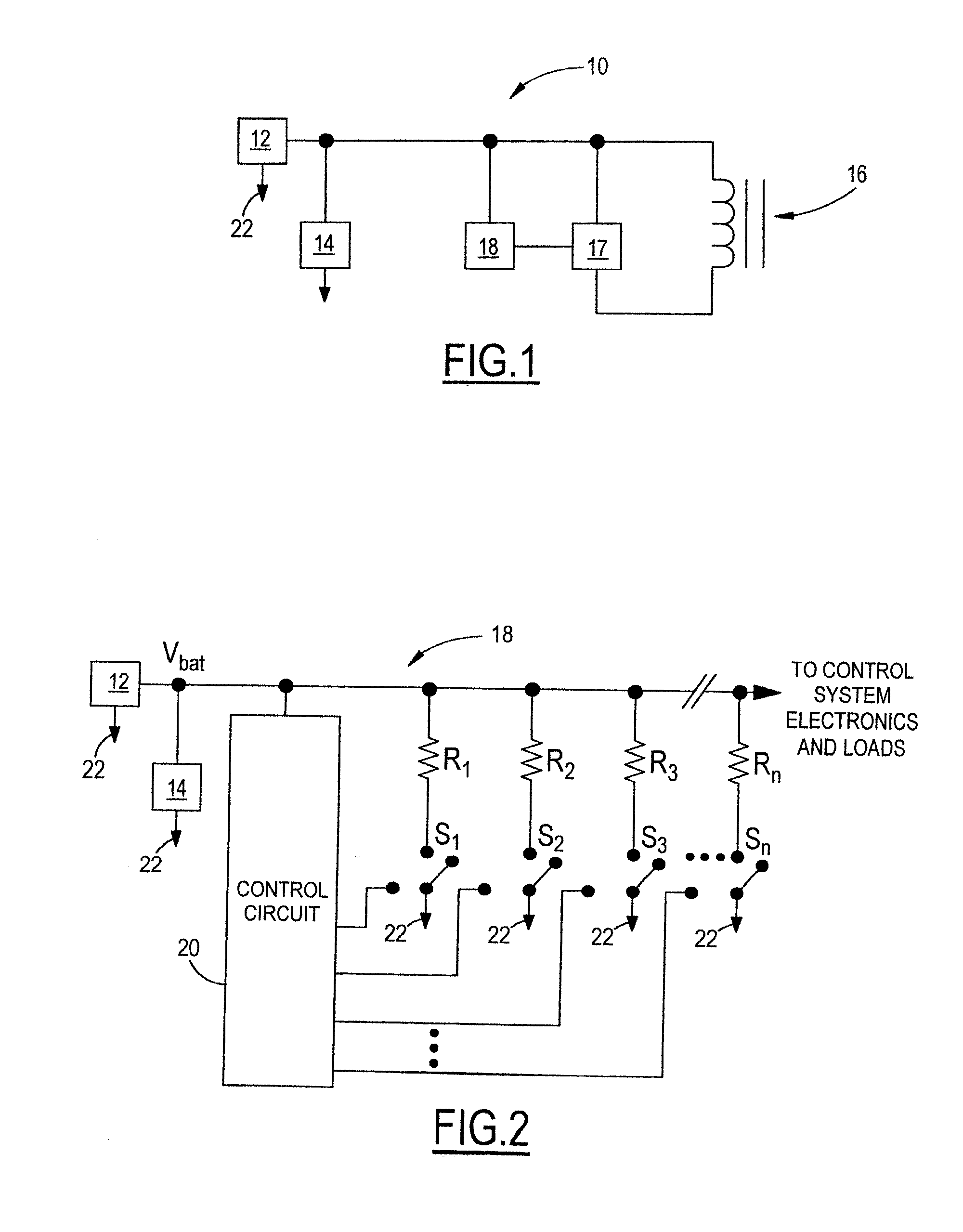
[0023]FIG. 1 is a schematic diagram of a model of a battery bus system 10 for an automotive electrical environment that would be subject to a protection circuit such as the load dump suppression control system and method of the present invention. An alternator 12 and a battery 14 are connected to each other and a protection circuit 18 for protecting sensitive control electronics 17 and a load 16. During load dump, the battery bus voltage, Vbat, will peak above its normal range, and without protection, permanent damage may occur to the sensitive electronics 17 and load 16.

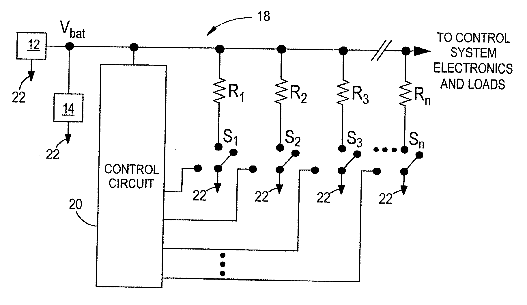
[0024]FIG. 2 shows an embodiment of the protection circuit 18 of the present invention as it would be applied in the circuit of FIG. 1. The protection circuit 18 has a control circuit 20 controlling a plurality of resistors, R1, R2, R3, through Rn. The resistors R1 through Rn are configured such that each resistor has a switch S1, S2, S3, through Sn, in order to independently adjust a combination of the resistors R1...


PUM


Abstract

An overvoltage protection system and method including a control circuit and a bank of resistors to absorb the energy from a transient voltage without exceeding an allowed temperature for the resistors. The resistors in the bank are independently switched and configured such that upon detection of an overvoltage condition a combination of the resistors is switched into the circuit to dissipate energy. The resistance introduced by the combination of resistors prevents the voltage from rising to an unacceptable level that may damage the circuit being protected. As time progresses, the control circuit alters the combination of resistors in the bank of resistors so as to increase the effective load resistance value, thereby decreasing a load current.

Description

TECHNICAL FIELD[0001]The present invention relates generally to electrical power protection circuits and more particularly to overvoltage protection circuits.BACKGROUND OF THE INVENTION[0002]Protection circuits are commonly used to protect electrical circuitry from exposure to transient surges of excessive voltages, known as overvoltage conditions. Overvoltage conditions occur when the voltage exceeds a particular circuit design capability. Overvoltage conditions may ultimately damage or destroy electrical components which is highly undesirable in any circuit design.[0003]An environment in which overvoltage may occur is a battery bus system for an automotive vehicle. In certain conditions, the vehicle's battery bus system voltage will peak above its normal range, commonly referred to as “load dump”. Without adequate protection, load dump can permanently damage the vehicle's electronic modules. For example, load dump may occur when jump-starting a vehicle. More specifically, the volt...

Claims


Application Information

Patent Timeline
IPC IPC(8): H02H9/04
CPCH02H3/006H02H7/067H02J7/0063H02J1/02H02J7/0029H02H9/042H02J7/00308H02J7/007182H02J7/1461G05F1/614H02H9/04
Inventor MULLIGAN, DAVID R.MILLER, JR., IRA C.
Owner VISTEON GLOBAL TECH INC
Why Eureka
Try Eureka