Thermal energy module

a technology of thermal energy modules and thermal energy storage, which is applied in the field of cold and hot thermal energy storage systems, can solve the problems of high energy consumption, high cost of gas turbines, and high cost of building, installation and operation of turbines, and achieves the effects of high energy efficiency, dissipation of energy, and high comfor

Inactive Publication Date: 2011-03-15
REICH DANIEL +2
View PDF25 Cites 23 Cited by
  • Summary
  • Abstract
  • Description
  • Claims
  • Application Information

AI Technical Summary

Benefits of technology

[0008]The present invention overcomes the disadvantages and limitations of the prior arts by providing a means of storage for not only cold, but also hot water energy which can be generated by solar heaters. Another advantage is that the proposed design is capable of a very high level of energy efficiency by retaining the extracted heat energy and reusing it for heating or hot water use, rather than dissipating this energy from the premises into the atmosphere as in most prior arts. The system is also capable of providing a considerably higher level of comfort over previous designs by gradually modulating the cooling and heating capacity and maintaining accurate temperature set points.
[0009]The main part of the invention is the Thermal Energy Module (TEM) comprising of an insulated flat tank with a flat heat exchanger located inside. The heat exchanger is comprised of two manifolds at the top and one at the bottom of the tank connected to a micro channel or pipe-in-plate panel which allows refrigerant liquid and vapor to move from the inlet manifold through the plates or channel down to the bottom manifold and then back up to the outlet manifold. The heat exchanger is located at the center section of the tank and its width is designed to prevent the water on the both sides of the tank from freezing during the ice generating process thereby providing pockets of unfrozen water where water jet generating inlet pipes are located. Both water jet pipes are connected to a manifold located at the top of the tank. The bottom of the tank contains a water outlet manifold. The heat exchanger also can be located in the tank in a way that its manifolds are located on the sides and the refrigerant is flowing horizontally. Top and bottom water manifolds are located inside insulation to prevent the water from freezing. Instead of water, other two-phase liquids can be used in this invention. The total thickness of the TEM tank can be made shallow enough to enable its incorporation inside wall framing of a typical building. Multiple TEMs can be built in array(s) in a wall or walls simultaneously serving as wall insulation. TEMs in an array can simultaneously work in different modes at any moment in time.

Problems solved by technology

These turbines are costly to build, install and operate and are typically used for only a very limited number of hours during the hottest days of the year.
The problem is typically this equipment is required to operate during the day, due to the lack of cost-effective, efficient energy storage.
And worse yet, the resulting demand in electricity consumption peaks requiring the use of low-efficiency gas turbine peak generators.
These systems are very complex, bulky, expensive and difficult to scale down for use in small commercial buildings or residential applications.
These types of systems are better suited for smaller buildings but they too suffer from being too complex, expensive and bulky for small businesses and homes.
Moreover, such systems do not provide a high level of comfort due to their inherent deficiency of controlling temperature by cycling the system on and off.
Also, these direct expansion systems can be used only for cooling purposes and are very difficult or impossible to combine with solar heating solutions which are becoming increasingly more important in energy conservation strategies.

Method used


Image

  • Thermal energy module
  • Thermal energy module
  • Thermal energy module

Examples


Embodiment Construction

[0024]The present invention is a means of storage for cold water (or similar energy transfer medium), ice, or hot water which may be generated by solar heaters wherein the means of storage allows for the ability to control demand and achieves a high level of energy efficiency by retaining extracted heat energy and reusing it for heating or generating hot water.

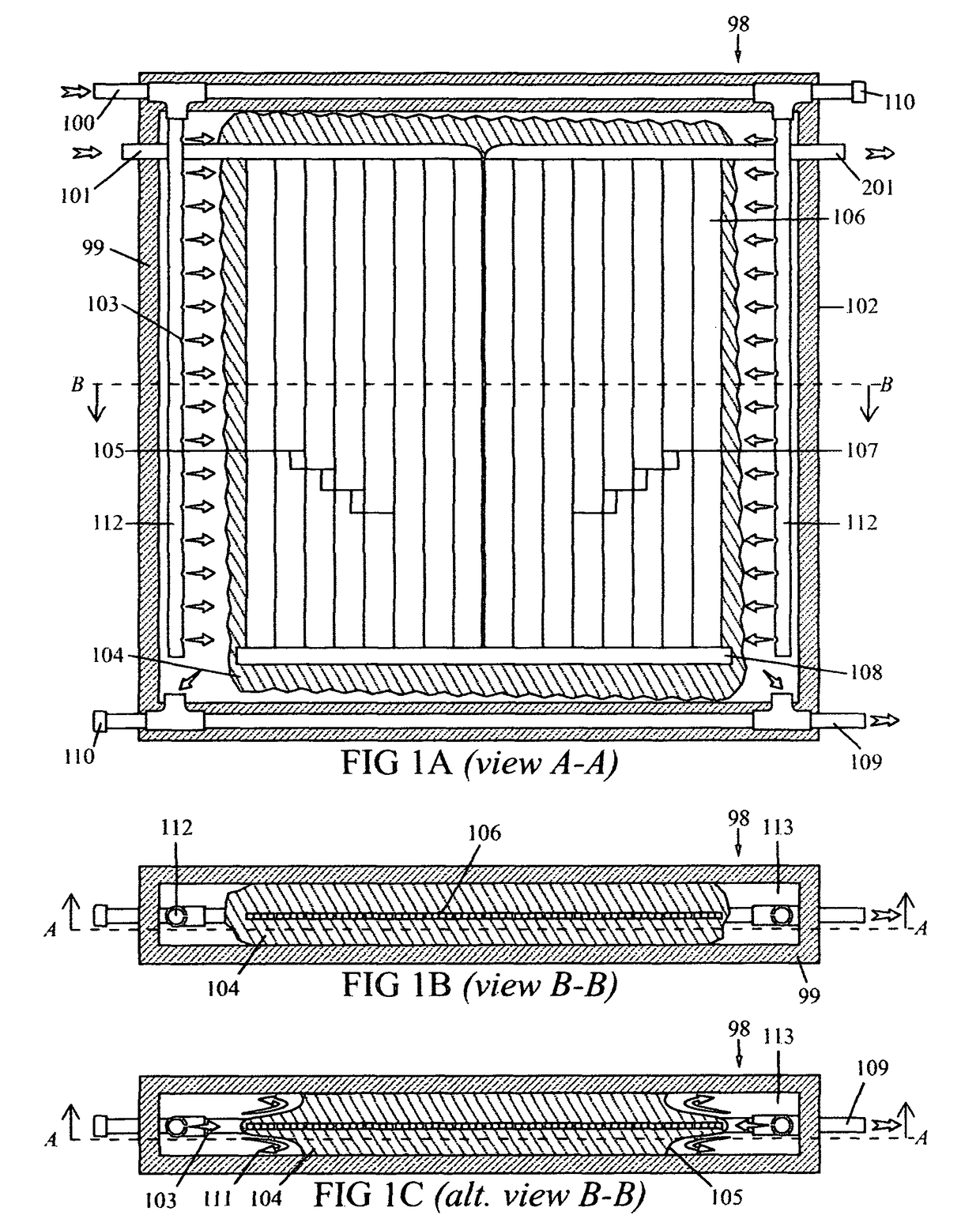
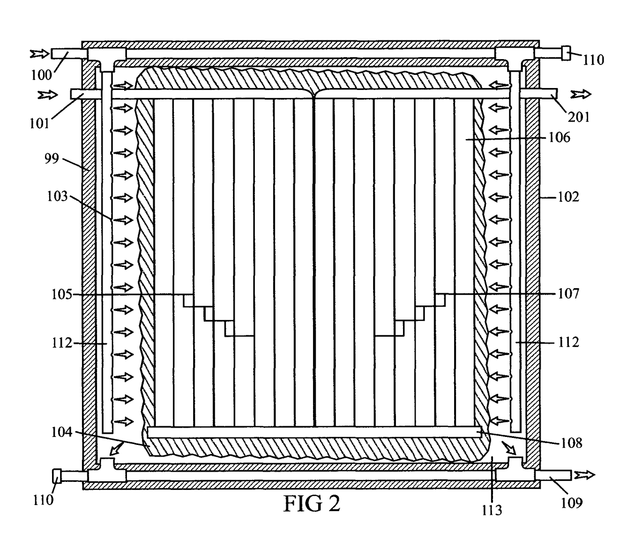
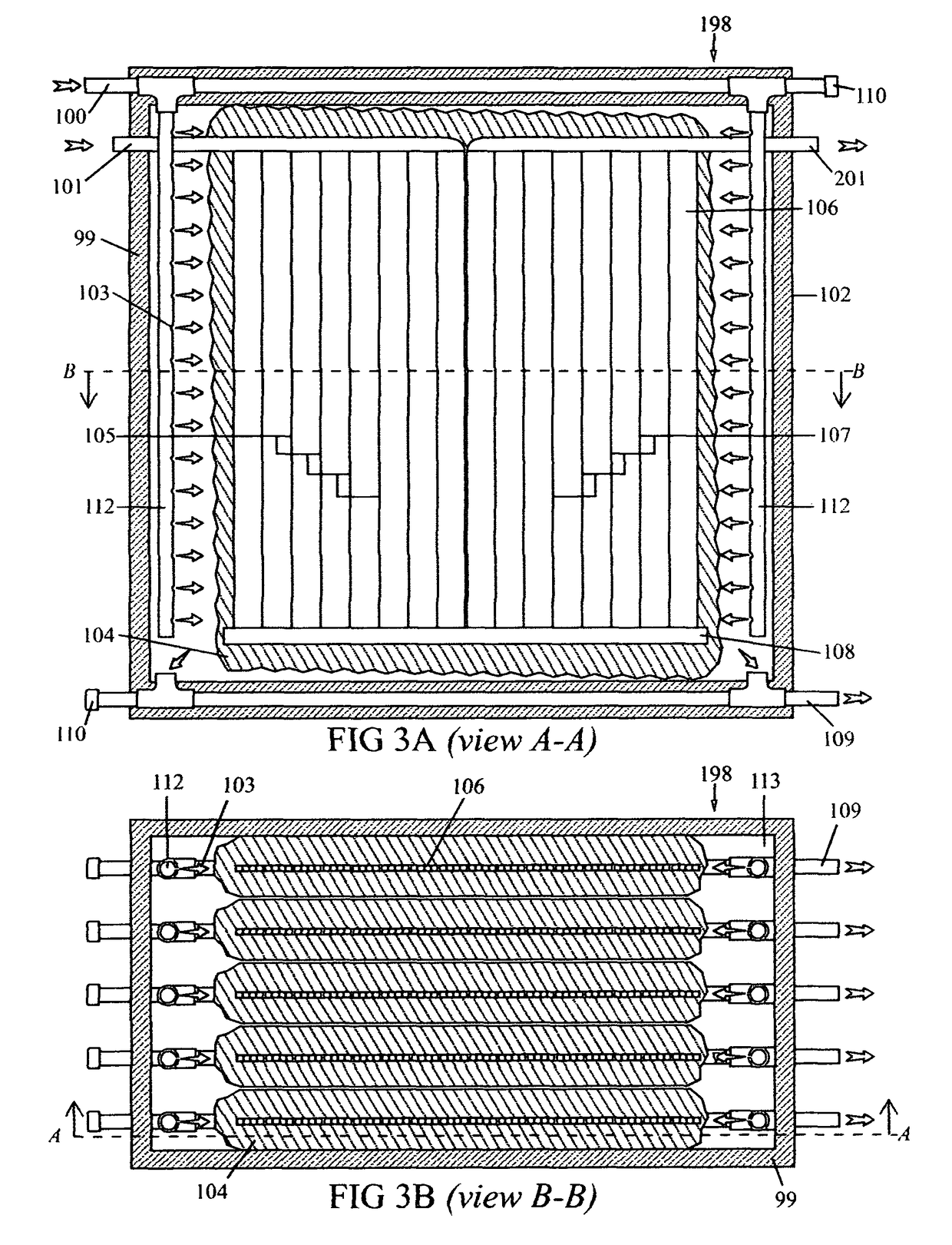
[0025]The present invention is a Thermal Energy Module comprising a tank and a flat heat exchanger. The heat exchanger is comprised of an intake manifold, a pass-through manifold, and an outlet manifold connected via micro-channel, pipe-in-plate panel, or similar thermal energy transfer structures which allow refrigerant liquid and vapor to move from the inlet manifold though a first energy transfer structure to the pass-through manifold and then through a second energy transfer structure to the outlet manifold. The heat exchanger is located within a tank and its size relative to the tank is designed to prevent ice from formin...


PUM


Abstract

The invention comprises a Thermal Energy Module comprising a tank adapted to hold water or other heat transfer medium (such as water), a water loop for introducing the heat transfer medium and removing the heat transfer medium, and a refrigeration loop comprising a heat exchanger further comprised of an inlet manifold, a heat transfer structure (such as a micro channel or pipe-in-plate panel) and an outlet manifold wherein the heat exchanger is adapted to transfer thermal energy between the heat transfer structure and the heat transfer medium. The Thermal energy Module may be utilized as a component of a heating and cooling system. Such a Thermal Energy Module may be used to store thermal energy during the day and return it during the evening. Additionally, such a Thermal Energy Module may be implemented as an array of such modules and such array of modules may be adapted to fit within the walls of a building or structure.

Description

BACKGROUND OF THE INVENTION[0001]1. Field of the Invention[0002]The present invention relates to cold and hot thermal energy storage systems as well as using such systems to optimize and reduce the electric and natural gas energy consumption of a building.[0003]2. Description of the Prior Art[0004]Improving the energy efficiency of building comfort systems has become progressively more important due to rising energy costs as well as increased awareness and concern over global warming as a result of humanity's rising consumption of carbon fuels for electrical energy generation, direct burn heating, and domestic hot water appliances. One area where these concerns can be addressed is through leveling demand by shifting some of the load during peak hours of a day to off-peak times, thereby eliminating the need to build and run expensive peak generator turbines. These turbines are costly to build, install and operate and are typically used for only a very limited number of hours during t...

Claims


Application Information

Patent Timeline
Patent Type & Authority Patents(United States)
IPC IPC(8): F25D16/00
CPCF28D20/0034F24F5/0035F25B39/02F25B29/003F28D20/021Y02E60/142Y02B30/545F25B2339/047F25B2400/24Y02B30/54Y02E60/14
Inventor REICH, DANIELBURDETT, MICHAELREICH, VLADIMIR
Owner REICH DANIEL
Why Eureka
Try Eureka