Electrode systems and methods of using electrodes

Active Publication Date: 2007-11-15
AGM CONTAINER CONTROLS
View PDF15 Cites 28 Cited by
  • Summary
  • Abstract
  • Description
  • Claims
  • Application Information

AI Technical Summary

Benefits of technology

[0009] The above-mentioned patent also discloses the use of a gas purge system in which the electrode is protected from the treatment gas by a shielding gas which is passed over the electrode and passes out of a chamber in which the electrode is located via a small hole provided therein. The shielding gas is provided at a higher pressure than the treatment gas, and thus acts to prevent any treatment gas entering the electrode chamber and being deposited thereon. The gas supply associated with the electrode can maintain the gas pressure around the electrode greater than in other areas of the evacuated chamber. These gases form a relatively high-density plasma associated with the electrode, which acts as an extension of the metallic electrode surface and lowers the impedance of the electrode. This electrode system is commonly known as a gas purged electrode. The benefit of using a gas purged electrode is that it provides a constant, low impedance electrical contact with the process plasma. Since the impedance is constant, the process does not drift; since impedance is low, the whole process operates at a lower voltage and less power is wasted. The greater gas pressures around the gas purged electrode are continually replenished by the gas supply, and the gas pressure differential between the area around the gas purged electrode and other areas of the evacuated chamber prevents reactive gases or other components from the main gas supply from approaching the gas purged counter electrode. The gas employed is generally an inert gas, such as helium, neon, or argon, or a mixture such as helium/neon or neon/argon. In reactive sputtering processes it can be oxygen, nitrogen or other reactive gases. Each of these gases may be used in the apparatus and method of the present invention.
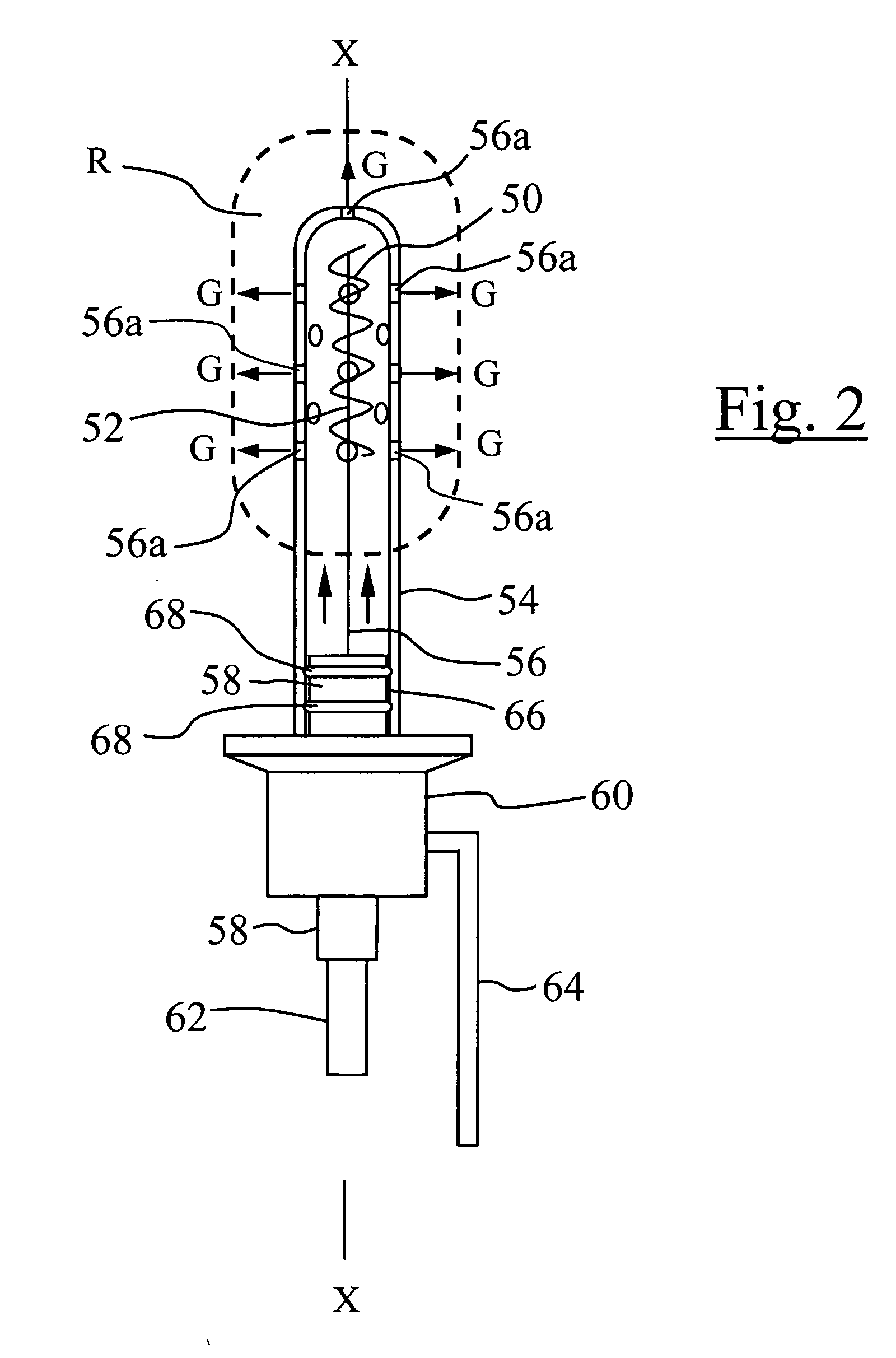
[0010] The present invention provides a gas purged electrode arrangement in which the electrode material is provided in the form of a metal coil having a longitudinal axis and the gas outlet is positioned for supplying plasma creating gas substantially along the longitudinal axis of said coil. It will be appreciated that the electrode may form an anode or a cathode. The coil creates a magnetic confinement field which assists with the confinement and intensification of the plasma field whilst electrons, including thermionically emitted electrons, and those flowing from the electrode material, are more readily confined within the field and acquire a high energy level before being released therefrom. In a particularly advantageous arrangement, the electrode material may be surrounded by a shield which effectively acts to encase the electrode material and further shield the electrode material from the main treatment gas within which the electrode material may be operated. The wall of the shield is provided with one or more outlets through which, in operation, the shielding gas passes into the treatment chamber. It has also been found that forming the electrode material into an arc or, preferably, a complete circular form helps intensify the energy of emitted electrons and, in some cases, can lead to a significant increase in the intensity of the plasma. In the case of an electrode material that is remote from the cathode, this arc geometry will provide full plasma activation of the entire diameter of gas volume as it flows between the cathode and electrode material, thus providing lower resistance than a straight electrode material. In each of the arrangements, it has been found that one can enhance the uniformity of emission by varying the number of outlets as the distance from the gas supply increases such that the number, or indeed size thereof, increases the further away the outlets are from the gas inlet. It has been found that an enhanced plasma effect can be created by angling the outlets around the circular electrode material arrangement such that the plasma emitted therefrom converges in a cone-like manner. Other forms of outlets, such as single outlets at the extremity of the shield or a plurality of outlets provided either along the shield or indeed circumferentially around the shield, may be employed and such arrangements are discussed in detail later herein. The electrode material is preferably made of a refractory material such as tantalum, tungsten or molybdenum as such materials are able to operate at elevated temperatures and, thereby, assist with the generation of enhanced numbers of thermionically emitted electrons.
[0011] In one preferred arrangement, the electrode comprises an electrode material formed as a coil having a longitudinal axis and a gas inlet for directing a shielding gas generally along the axis whilst being confined by a shield arrangement surrounding the electrode material. The shield is provided with an outlet in a surface thereof so as to allow for the passage of plasma gas out of said shield. Such an arrangement provides both enhanced electron generation and shielding of the electrode material from the potentiall

Problems solved by technology

One problem in such systems is that the electrodes can become contaminated with an insulating layer of the material intended for the component.
The growth of deposits on the electrodes will result in a shift of the voltage/current characteristics of the system over time and the required operating voltage will increase for a given current as contamination of the electrode progresses.
These changes cause a drift in the quality of the dielectric coating produced on the substrate, and require periodic cleaning or replacement of the electrodes.
Furthermore, due to the high impedance presented to the plasma by a contaminated electrode, power will be wasted and excess heat generated.
A simi

Method used


Image

  • Electrode systems and methods of using electrodes
  • Electrode systems and methods of using electrodes
  • Electrode systems and methods of using electrodes

Examples


Embodiment Construction

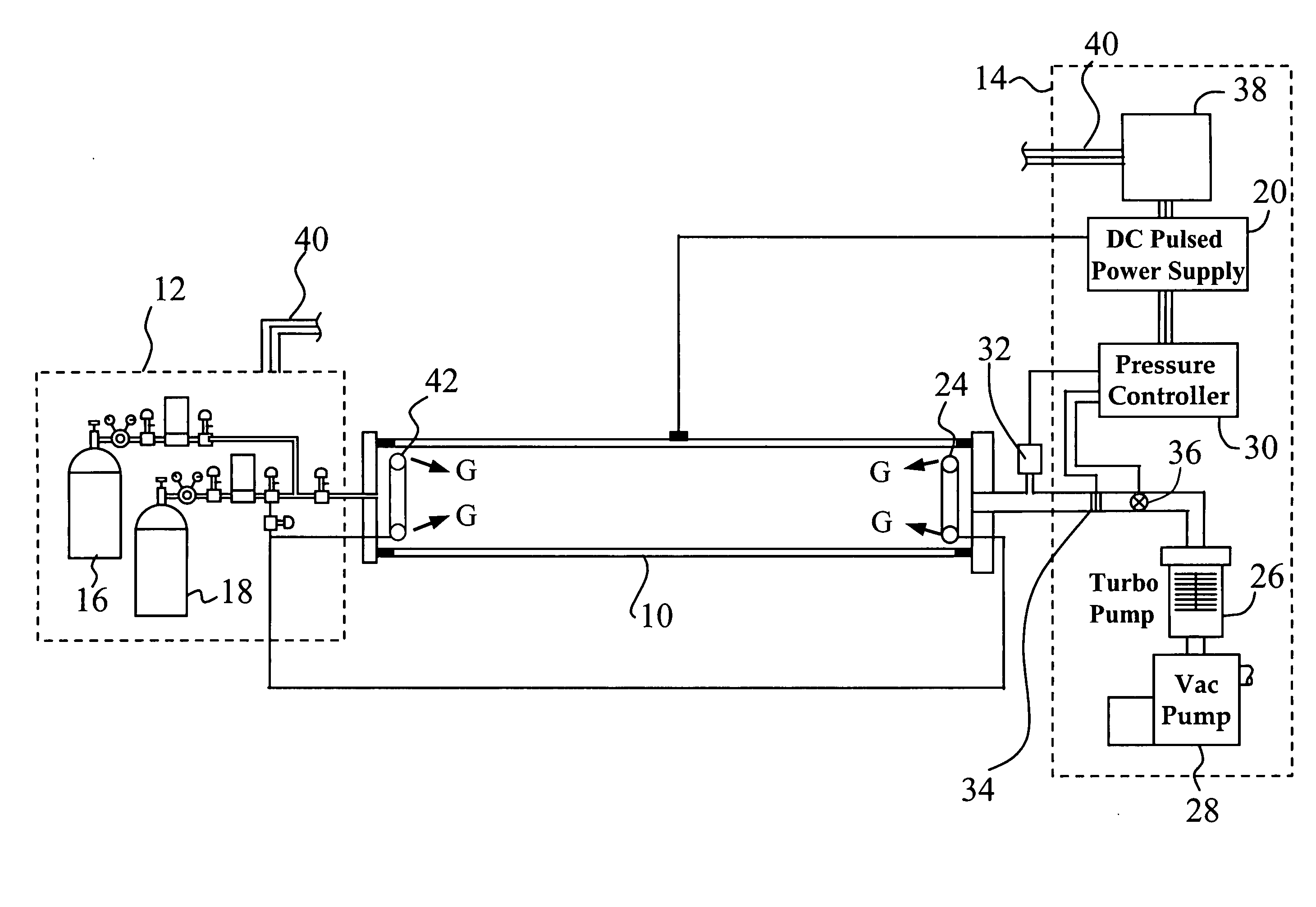
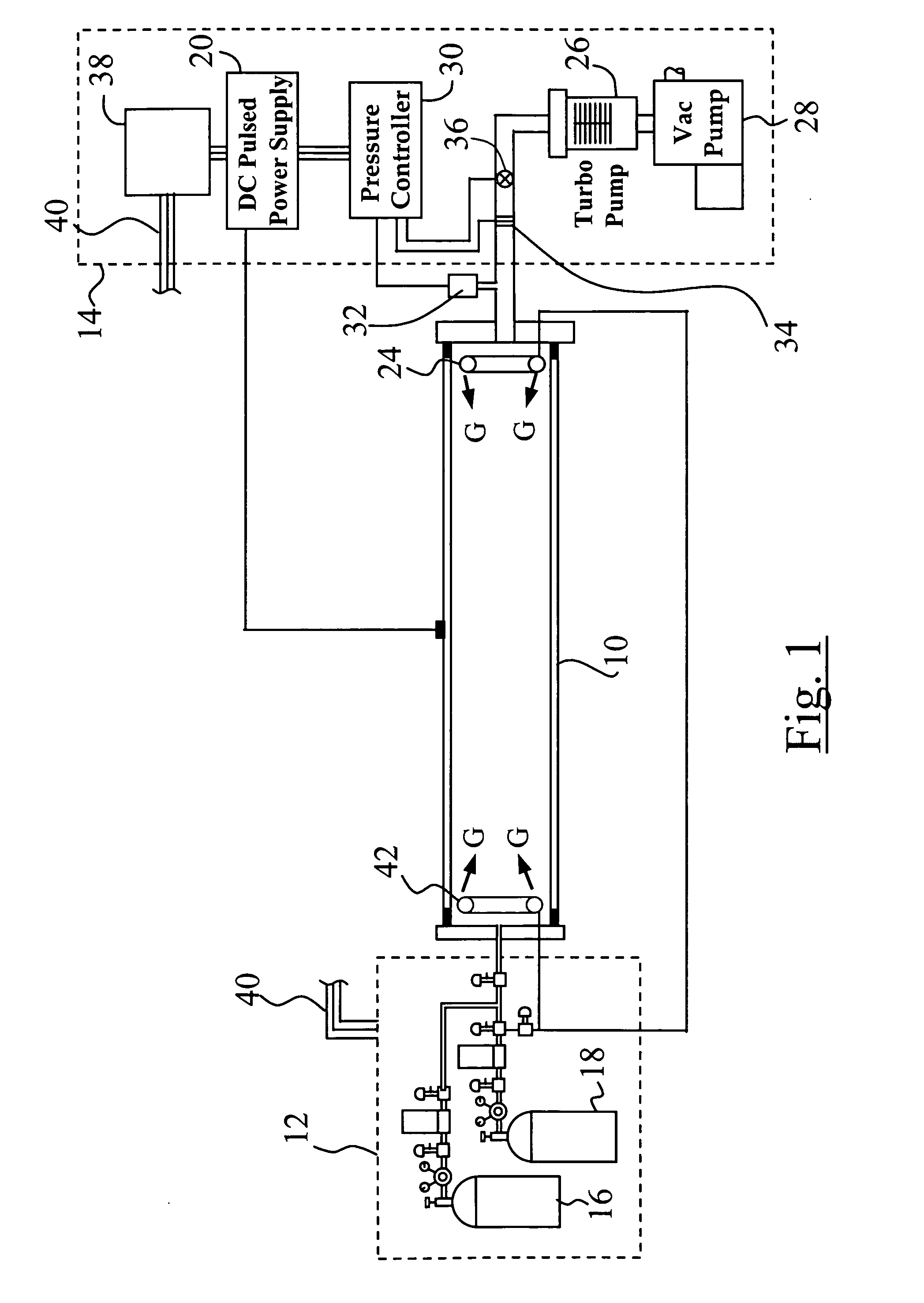
[0023] With reference to FIG. 1, a conductive piping, or “workpiece,”10 is shown as being connected to a system that includes a gas supply subsystem 12 and a process control subsystem 14. The workpiece is shown as a single piece, but may be an assembly of tubes or pipes. A readily available treatment gas, such as methane or acetylene, is provided in a first gas supply container 16. This gas is used in implantation or coating steps described later herein. Argon or any other suitable inert gas fit for the purpose is provided from a second gas supply container 18 to allow plasma “pre-cleaning” of the pipe surface and mixing of Argon (Ar) and treatment gas.

[0024] A DC pulsed power supply 20 is used to apply a negative bias to the workpiece 10. This bias is used to (a) create a plasma between a cathode and a grounded electrode material, (b) draw an ionized reactive gas to the surfaces to be treated, (c) allow ion bombardment of the film to improve film properties such as density and str...


PUM

PropertyMeasurementUnit
Diameteraaaaaaaaaa
Lengthaaaaaaaaaa
Diameteraaaaaaaaaa

Abstract

An electrode assembly comprises a coil of electrode material surrounded by a shield having one or more outlets and a supply of shielding gas directed along an axis X-X of said coil before exiting from said shield.

Description

TECHNICAL FIELD [0001] The present invention relates to deposition and material modification processes and system for use therewith and relates particularly but not exclusively to plasma enhanced chemical vapor deposition or material modification processes, electrodes used in such systems and methods of using such electrodes. BACKGROUND ART [0002]“Plasma enhanced chemical vapor deposition” (or PECVD) is a known technique used to form films on various substrates. For example, Felts et al. U.S. Pat. No. 5,224,441 describes an apparatus for rapid plasma deposition. In the plasma enhanced chemical vapor deposition of silicon oxide, a gas stream including components such as a volatilized organosilicon compound, oxygen, and an inert gas such as helium or argon, is sent into an enclosed chamber at reduced pressure and a glow discharge plasma is established from the gas stream or its components. A silicon oxide layer is deposited upon the substrate when it is positioned near the plasma. In ...

Claims


Application Information

Patent Timeline
IPC IPC(8): B23K9/00
CPCH01J37/32541
Inventor BOARDMAN, WILLIAM JOHNTUDHOPE, ANDREW WILLIAMMERCADO, RAUL DONATECASSERLY, THOMAS BRYAN
Owner AGM CONTAINER CONTROLS
Why Eureka
Try Eureka