Source driver and liquid crystal display

Inactive Publication Date: 2009-12-24
NOVATEK MICROELECTRONICS CORP
View PDF9 Cites 0 Cited by
  • Summary
  • Abstract
  • Description
  • Claims
  • Application Information

AI Technical Summary

Benefits of technology

[0010]The present invention is directed to a source dri

Problems solved by technology

If the charging time T is excessive long, it may in

Method used


Image

  • Source driver and liquid crystal display
  • Source driver and liquid crystal display
  • Source driver and liquid crystal display

Examples


Example

First Embodiment

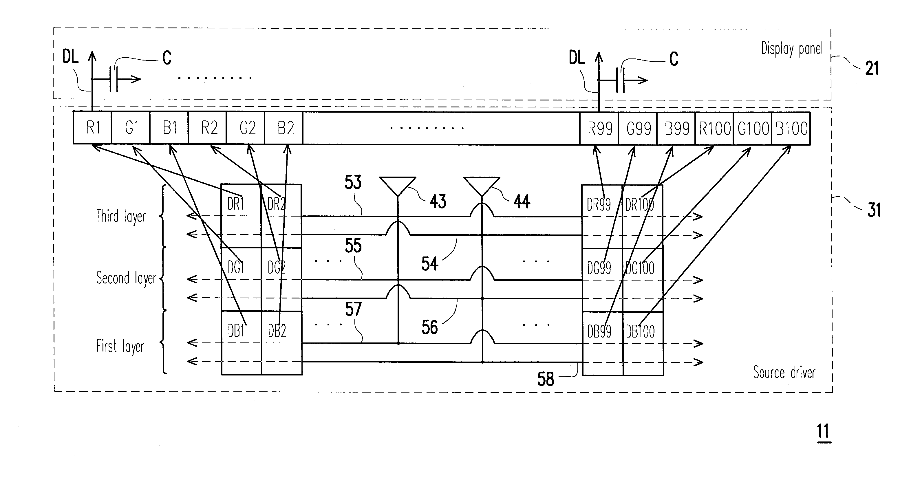
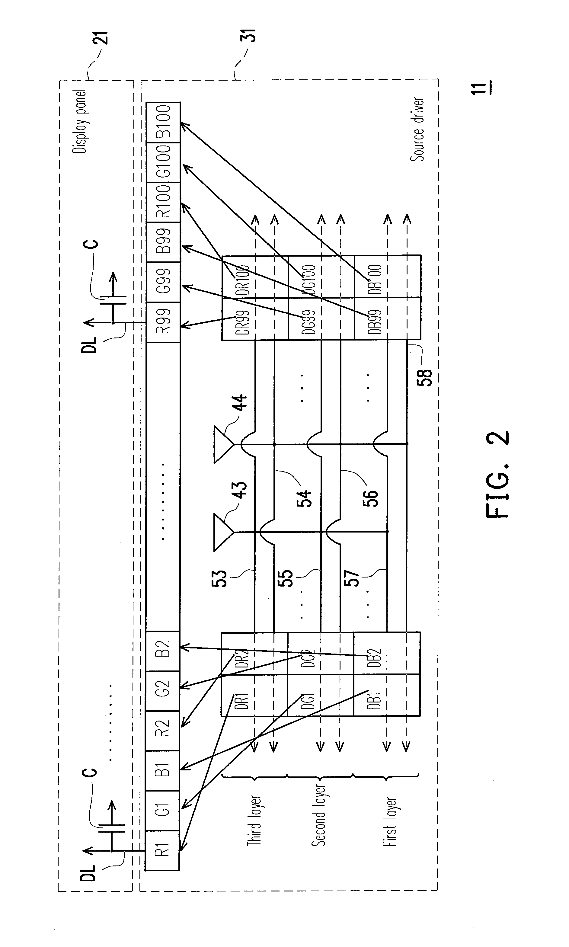
[0026]FIG. 2 is a schematic diagram illustrating an LCD according to a first embodiment of the present invention. Referring to FIG. 2, the LCD 11 includes a display panel 21 and a source driver 31. The display panel 21 may include a pixel array (not shown), a plurality of scan lines (not shown) and a plurality of data lines DL, wherein the pixel array is coupled to the scan lines and the data lines DL. The source driver 31 may include buffer amplifiers 43 and 44, conducting wires 53-58, DACs DR1-DR100, DG1-DG100 and DB1-DB100, and pads R1-R100, G1-G100 and B1-B100.

[0027]The buffer amplifier 43 is coupled to the conducting wires 53, 55 and 57. The buffer amplifier 44 is coupled to the conducting wires 54, 56 and 58. The conducting wires 53 and 54 are respectively coupled to the DACs DR1-DR100. The conducting wires 55 and 56 are respectively coupled to the DACs DG1-DG100. The conducting wires 57 and 58 are respectively coupled to the DACs DB1-DB100. The DACs DR1-DR100 ...

Example

Second Embodiment

[0034]FIG. 3 is a schematic diagram illustrating an LCD according to a second embodiment of the present invention. Referring to FIG. 2 and FIG. 3, in the first embodiment, the buffer amplifiers 43 and 44 of the source driver 31 are respectively used for providing a gamma voltage to the three hundred DACs. Though, in other embodiments, different number of the buffer amplifiers can be disposed in the source driver to provide the gamma voltage to the DACs. For example, in a source driver 32 of the present embodiment, four buffer amplifiers 45, 46, 45′ and 46′ are applied. To be more specific, the buffer amplifiers 45 and 46 respectively provide the gamma voltage to the DACs DR1-DR50, DG1-DG50 and DB1-DB50, and the buffer amplifiers 45′ and 46′ respectively provide the gamma voltage to the DACs DR51-DR100, DG51-DG100 and DB51-DB100.

[0035]The buffer amplifiers 45, 46, 45′ and 46′ respectively provide the gamma voltage to the one hundred and fifty DACs, while the buffer a...

Example

Third Embodiment

[0036]FIG. 4 is a schematic diagram illustrating an LCD according to a third embodiment of the present invention. Referring to FIG. 2 and FIG. 4, a source driver 33 of the LCD 13 applies six buffer amplifiers 47, 48, 47′, 48′, 47″ and 48″. The buffer amplifiers 47″ and 48″ are disposed in the first layer for respectively providing the gamma voltage to the DACs DB1-DB100. The buffer amplifiers 47′ and 48′ are disposed in the second layer for respectively providing the gamma voltage to the DACs DG1-DG100. The buffer amplifiers 47 and 48 are disposed in the third layer for respectively providing the gamma voltage to the DACs DR1-DR100. In the present embodiment, the buffer amplifiers 47, 48, 47′, 48′, 47″ and 48″ of the source driver 33 respectively provide the gamma voltage to the one hundred DACs, and the buffer amplifier 43 and 44 of the source driver 31 of the first embodiment respectively provide the gamma voltage to the three hundred DACs. Compared to FIG. 2, the ...


PUM


Abstract

A source driver and a liquid crystal display are provided. The source driver includes a plurality of pads, a first conducting wire, a second conducting wire, a plurality of first digital-to-analog converters (DACs), and a plurality of second DACs. The first conducting wire is coupled to a first voltage and the first DACs. The second conducting wire is coupled to a second voltage and the second DACs. The first DACs are disposed in a first layer. Output terminals of the first DACs are respectively coupled to a plurality of first pads included in the said pads. The second DACs are disposed in a second layer above the first layer. Output terminals of the second DACs are respectively coupled to a plurality of second pads included in the said pads. Thereby, the transmission quality of the conducting wires for transmitting signals is increased.

Description

CROSS-REFERENCE TO RELATED APPLICATION[0001]This application claims the priority benefit of Taiwan application serial no. 97123184, filed Jun. 20, 2008. The entirety of the above-mentioned patent application is hereby incorporated by reference herein and made a part of this specification.BACKGROUND OF THE INVENTION[0002]1. Field of the Invention[0003]The present invention relates to a liquid crystal display. More particularly, the present invention relates to a source driver.[0004]2. Description of Related Art[0005]Source driver is an important component within a thin film transistor liquid crystal display (TFT LCD), which can convert a digital signal required for displaying images into an analog signal, and transmits the analog signal to each sub-pixel (or referred to as dot) of the TFT LCD.[0006]Generally, buffer amplifiers of the source driver are disposed between digital-to-analog converters (DAC) and output pads, though such method requires a plenty of buffer amplifiers. To red...

Claims


Application Information

Patent Timeline
IPC IPC(8): G09G3/36H03M1/66
CPCG09G3/3688G09G2320/0223G09G2310/027
Inventor HUANG, LI-CHUN
Owner NOVATEK MICROELECTRONICS CORP
Why Eureka
Try Eureka