However, single-ended signaling systems actually require more circuitry per channel than just one signal conductor.
However, it is fundamentally difficult to ensure agreement on the value of the reference
voltage between transmitter and
receiver and agreement is needed to ensure consistent interpretation of the signals sent by the transmitter to the
receiver.
Finally, single-ended systems are more susceptible to externally coupled
noise sources compared with differential systems.
For example, if
noise is electromagnetically coupled to a signal conductor of a single-ended
system, the
voltage that arises from this
coupling arrives as un-cancelled noise at the receiver.
Unfortunately, such noise
coupling is often from neighboring wires in a bundle of single-ended signals, called cross-talk, and this noise source is proportional to the signal
voltage level, and therefore cannot be overcome by increasing the
signal level.
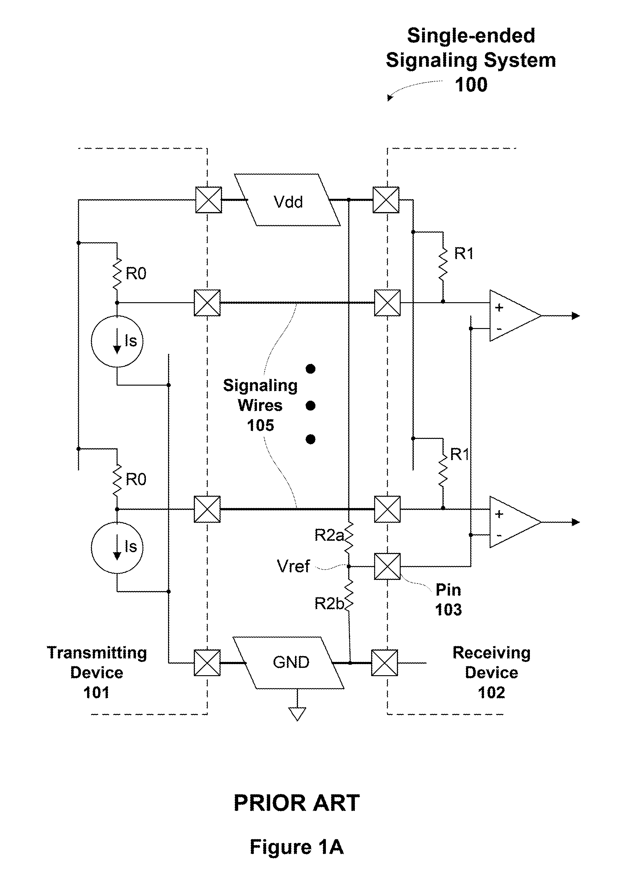
A first problem with the
external reference voltage technique shown in FIG. 1A, is that the
external reference voltage is developed across external resistors R2a and R2b between the power supply terminals Vdd and GND, and that the generated
external reference voltage cannot be matched with the voltage developed by the current sources in the transmitting device 101, since the current sources are completely uncorrelated with the external resistors R2a and R2b.
A second problem is that the
power supply voltage at the receiving device 102 may be different from the
power supply voltage at the transmitting device 101, since the supply networks to the two communicating chips have different impedances, and the two chips draw different, and variable, currents.
A third problem is that noise injected into any one of the signaling wires 105
coupling the transmitting device 101 to the receiving device 102 is not injected into the reference voltage, and therefore the
signaling system must budget for the worst case noise voltage that may be introduced to the signaling wires 105.
A fourth problem is that the voltage level between the external power supply terminals Vdd and GND differs from the internal power
supply network within the receiving device 102, again because of the supply impedance.
However, the noise coupling problems of the external reference voltage approach described in conjunction with FIG. 1A remain.
Cancellation of the common-mode noise cannot be perfectly effective however, because the bundled reference voltage has terminating impedance at the receiving device 132 that is different from a
data signal; since the bundled reference voltage must be fanned out to a large number of receivers, the
capacitance on the pin receiving Vref is always larger than on a typical signal pin, so noise is low-passed, relative to a
data signal.
In addition, the
inductance is in series with the terminator and will cause reflections in the signaling channels, yet another source of noise.
Since the steady-state current path is different from the transient one, there is a transition between the two conditions in which
transient current flows in both Vdd and ground networks, dropping voltages across the supply impedances, and generating more noise.
This choice would not solve the basic problem, however.
The fundamental problems are two-fold: first, the shared supply impedances are a source of cross-talk and supply noise.
Second, the split in signal current between the two supplies makes it difficult to keep the
return current physically adjacent to the signal current through the channel, which leads to poor termination and reflections.
When all of the data pins that share a common set of Vdd / ground terminals are switching, the noise in the shared impedances is additive, and the magnitude of the noise comes directly out of the signaling noise budget.
It is difficult and expensive to combat this noise: reducing the supply impedances generally requires providing more power and ground pins and / or adding more
metal resources on chip to reduce impedances.

